You know, I really sympathize with this plea.Nazaroo,
It may be a great amp design and I applaud your hard work. But this forum is called DIY for a reason. If you were willing to give us a schematic, with values, that we could reproduce, that would be great. I'm sure there are people here that could figure out the values for all those resistors. But I can't.
I have felt that "I feel stupid" feeling many times.
Its so difficult to be the one in class who has to put up his hand and ask the 'dumb question',
especially when you know there are at least ten others
who want to ask it, but are too embarrassed to do it.
So I take this as manning up.
I'll step you through the circuit a bit.
And it feels to me like the rich kid waving the keys to his Ferrari in my face. I'd still love the car, the owner, not so much. If you aren't really willing to share your post here seems pointless to me. And your tone doesn't help your case either.
LOL.
I hate rich people, because I've been poor a long time.
But I won't dump those sour grapes here.
I'll only laugh and say shoe's on the other foot.
You don't know it yet, but I've already shared too much.
But I don't really worry about it anymore.
I'd rather help the many that need it than worry about the one creepy guy who steals my ideas,
but is so thick he has to ask me to hold his hand while he does it.
I already figured out long ago that having a brilliant idea doesn't make you a genius.
If someone steals your idea you haven't lost anything.
A real song-writer isn't a one-hit wonder. Its his daily craft.
A real genius pumps out brilliant ideas every day,
and doesn't have to worry if someone takes one and uses it.
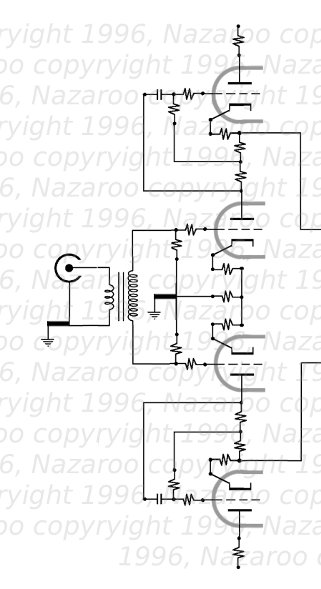
Okay lets look at the input / stage 1.
Overview:
What is going on here?
First of all, I chose balanced stages all the way through the amp.
We have to get to balanced anyway, for a Push-Pull at the output stage,
so at some point I'd need an interstage transformer or a splitter, with all those problems:
added stages, another layer of distortion etc.
Well I learned a lesson working with professional studio gear, which is balanced all the way from the microphone.
It works best, and gives the highest noise immunity and lowest distortion.
All the advantages of the Push-Pull (harmonic cancellation, Powersupply noise cancellation)
are now transferred to the whole amp.
If the Mu-Follower wasn't clean enough, its now bullet-proof.
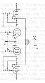
What you are looking at is two Mu-followers, one for each side of a balanced input.
One is drawn upside down for symmetry and beauty.
The input transformer is a Jensen.
Simply put they make the best input transformers you can buy.
We use them in everything in a studio environment, for isolation, balance, and frequency-response, noise immunity, and low distortion.
They are a cost-effective solution and replace an interstage transformer, which,
to get the same specs would cost a fortune, and they don't make them like this anyway.
Jensen can make near-perfect transformers because of the signal amplitude and size.
Nuff said. No one in their right mind would prefer an interstage to an input transformer.
That leaves the resistor values.
The input stage here could be any tube, but lets pick a 12AX7A
just to keep it easy to get good quality cheaply available parts.
Well, we'd like about 250 volts across each tube.
We'd like to bias them according to my little method.
But people have designed plenty of 12AX7 Mu-Followers,
and you can use tested circuits that are known to deliver high fidelity.
Some things never change.
The input grid resistor for each triode should be 500k to 1Meg R.
This provides an appropriate input impedance for the transformer,
and a path to ground to (self-)bias the grid.
The cathode resistor should be about 1k R to give a volt or two of self-bias.
It's positive voltage at the top (due to the idle current) makes the grid relatively negative.
Input tubes should pretty much always be self-biased unless you have a good reason not to.
If you are using a 6922 or some other more sensitive tube, don't forget a grid-stopper (shown).
Otherwise you risk hidden parasitic oscillation and poor performance.
You'll notice I have a three-resistor network to ground for the two bottom tubes (one upside-down).
That's Hafler's minimum IM distortion trick, discussed in the literature.
You can just as easily use a couple of LED diodes to ground on the bottom tubes (NOT the top ones!!!),
as some people are doing these days (they weren't available in Hafler's day).
The top tubes are set up similarly, but the extra resistor on the cathode is another parasitics-stopper (horizontal, optional).
Again a 500K resistor (or 1 Meg R) is a grid-leak or input resistor (and a horizontal grid stopper if needed: try 1k).
The top resistor is not really a load resistor, its again a 'parasitics stopper' resistor. (500 R would do, or even skip it).
The top tube is operating as a cathode follower.
The input cap for the top tubes are .22 uF, but you could use a .1 uF, its not critical.
What's left? The input is grounded to the chassis- via a star-ground at the bottom of the input tubes.
This is for shielding, but it can be skipped, and you could just use an XLR input for a balanced line input.
You could even eliminate the input transformer entirely if you have balanced lines.
Any questions? No, then we can move on to the next (last) stage.
Overview:
What is going on here?
First of all, I chose balanced stages all the way through the amp.
We have to get to balanced anyway, for a Push-Pull at the output stage,
so at some point I'd need an interstage transformer or a splitter, with all those problems:
added stages, another layer of distortion etc.
Well I learned a lesson working with professional studio gear, which is balanced all the way from the microphone.
It works best, and gives the highest noise immunity and lowest distortion.
All the advantages of the Push-Pull (harmonic cancellation, Powersupply noise cancellation)
are now transferred to the whole amp.
If the Mu-Follower wasn't clean enough, its now bullet-proof.
What you are looking at is two Mu-followers, one for each side of a balanced input.
One is drawn upside down for symmetry and beauty.
The input transformer is a Jensen.
Simply put they make the best input transformers you can buy.
We use them in everything in a studio environment, for isolation, balance, and frequency-response, noise immunity, and low distortion.
They are a cost-effective solution and replace an interstage transformer, which,
to get the same specs would cost a fortune, and they don't make them like this anyway.
Jensen can make near-perfect transformers because of the signal amplitude and size.
Nuff said. No one in their right mind would prefer an interstage to an input transformer.
That leaves the resistor values.
The input stage here could be any tube, but lets pick a 12AX7A
just to keep it easy to get good quality cheaply available parts.
Well, we'd like about 250 volts across each tube.
We'd like to bias them according to my little method.
But people have designed plenty of 12AX7 Mu-Followers,
and you can use tested circuits that are known to deliver high fidelity.
Some things never change.
The input grid resistor for each triode should be 500k to 1Meg R.
This provides an appropriate input impedance for the transformer,
and a path to ground to (self-)bias the grid.
The cathode resistor should be about 1k R to give a volt or two of self-bias.
It's positive voltage at the top (due to the idle current) makes the grid relatively negative.
Input tubes should pretty much always be self-biased unless you have a good reason not to.
If you are using a 6922 or some other more sensitive tube, don't forget a grid-stopper (shown).
Otherwise you risk hidden parasitic oscillation and poor performance.
You'll notice I have a three-resistor network to ground for the two bottom tubes (one upside-down).
That's Hafler's minimum IM distortion trick, discussed in the literature.
You can just as easily use a couple of LED diodes to ground on the bottom tubes (NOT the top ones!!!),
as some people are doing these days (they weren't available in Hafler's day).
The top tubes are set up similarly, but the extra resistor on the cathode is another parasitics-stopper (horizontal, optional).
Again a 500K resistor (or 1 Meg R) is a grid-leak or input resistor (and a horizontal grid stopper if needed: try 1k).
The top resistor is not really a load resistor, its again a 'parasitics stopper' resistor. (500 R would do, or even skip it).
The top tube is operating as a cathode follower.
The input cap for the top tubes are .22 uF, but you could use a .1 uF, its not critical.
What's left? The input is grounded to the chassis- via a star-ground at the bottom of the input tubes.
This is for shielding, but it can be skipped, and you could just use an XLR input for a balanced line input.
You could even eliminate the input transformer entirely if you have balanced lines.
Any questions? No, then we can move on to the next (last) stage.
Attachments

Last edited:
Nazaroo,
I didn't mean to be rude. I guess its my own inability to design a circuit that brought that out. But I love tubes and music. And when someone tells me they have the greatest thing since sliced bread and then I can't have a slice it kinda bothers me.
Do I have your permission to try to build it?
I didn't mean to be rude. I guess its my own inability to design a circuit that brought that out. But I love tubes and music. And when someone tells me they have the greatest thing since sliced bread and then I can't have a slice it kinda bothers me.
Do I have your permission to try to build it?
Sorry, one more important detail.
On average, if you build my circuits,
you are going to be playing with DOUBLE the normal high voltages
that are normally seen in tube amps.
You have now moved from annoyingly painful to lethal operations!!
Please please please bone up on all the safety-rules you can find.

I have some critically important rules too:
If you build them for yourself, make sure that
NO KIDS OR PETS can get near them!
If one were to poke one or fall on it that would be the end.
And,
NEVER build one for someone else, without a childproof CAGE OVER IT.
Theres a reason governments require commercial makers to provide them.
To hand a child a loaded gun is a form of negligent homicide.
This is the same thing.
Once its out of your hands, you can't predict what stupid thing might happen next.
Take all necessary precautions and save lives.
You must self-bias all tubes.
On average, if you build my circuits,
you are going to be playing with DOUBLE the normal high voltages
that are normally seen in tube amps.
You have now moved from annoyingly painful to lethal operations!!
Please please please bone up on all the safety-rules you can find.
I have some critically important rules too:
If you build them for yourself, make sure that
NO KIDS OR PETS can get near them!
If one were to poke one or fall on it that would be the end.
An externally hosted image should be here but it was not working when we last tested it.
And,
NEVER build one for someone else, without a childproof CAGE OVER IT.
Theres a reason governments require commercial makers to provide them.
To hand a child a loaded gun is a form of negligent homicide.
This is the same thing.
Once its out of your hands, you can't predict what stupid thing might happen next.
Take all necessary precautions and save lives.
You must self-bias all tubes.
Last edited:
Too many absolutist claims for my taste. There's more than one way to skin a cat; you do not hold a patent on what is 'best'. A little more humility would help support the claim that you stand on the shoulders of giants.
What claims?Too many absolutist claims for my taste.
I'm just recording some useful history here.
I don't like the innuendos or connotations.There's more than one way to skin a cat; you do not hold a patent on what is 'best'.
I'm sure there will be other amps that sound as good as mine.
The challenge would not be that,
but to build one as cost-effectively.
Good luck with that.
By all means post a cheaper way to get 40 watts per channel of pure sound.
Especially if you poo poo a design topology
before you even build it.
How humble do you want it?A little more humility would help support the claim that you stand on the shoulders of giants.
If you're going to spank me, and make me beg,
you better be a pretty hot redhead with green eyes
and a killer body.
Otherwise forget it, you don't have enough money to buy the show.
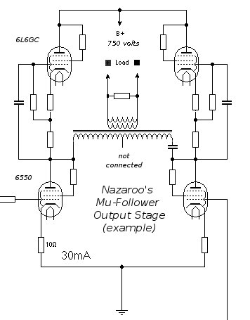
Since your H-bridge have to operate in class A, why run the KT88s at 30 mA?
Since your H-bridge have to operate in class A, why run the KT88s at 30 mA?
the 30 mA was left over from the circuit-board drawing
in this thread here.
You are looking at a quick addition to a horribly designed amp there by someone else in another thread.
I probably shouldn't have posted this pic.
It was an ad hoc fix to a crappy amp.
I initially posted it as an illustration of my output stage,
before I decided to post a full schematic.
While we're at it, lets look at the real output stage:
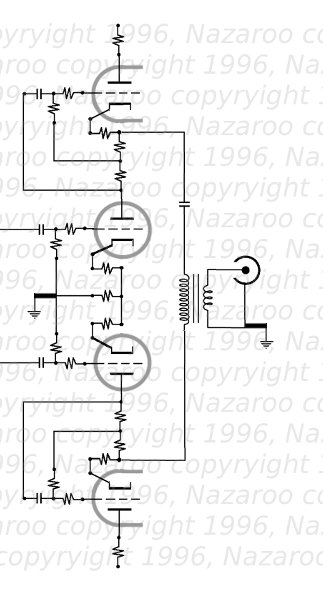
Again we see balanced-input complimentary Mu-Follower circuits,
each providing 1/2 of the P to P voltage across the transformer.
The nice thing is, there is no DC flowing through the OT.
The tubes get their current from the Power Supply through the top tubes,
and the OT route is superfluous.
The blocking cap I used was 10 uF, 600v polyprop, the only expensive cap in the whole amp.
It's also bypassed with a fastcap low esr, just in case.
The cap should not face any voltage other than the output signal.
If there were a slight imbalance between the tubes,
and a small DC voltage difference between the two tapping points,
who cares? its blocked.
The beauty of this is that the tubes don't even have to be balanced, as in a std Push-Pull.
The DC offset can't dump any current into the tranny, so there's no concern at all.
The tubes would have to be woefully out of wack to have any effect on the signal.
Since this is a constant-current style circuit, operating high in Class-A,
there is no question at all of 'blocking-distortion' from grid current in the bottom tubes.
But still the input grid-leak resistors should be as recommended by tube-makers,
e.g., for a 6550 say 100k and an appropriate input cap, say 1 uF.
Again with the Hafler cathode circuit, which minimizes Push-Pull IM.
What can I say?
These output tubes have to be self-biased, because of the huge high voltages across the circuit.
But thats okay, because the Mu-Follower forces linearity on both tubes,
even before they have to cancel out small non-linearities from each other.
Win win again.
Use large wattage cathode resistors, and adequate ventilation.
Don't forget sensible grid-stoppers and screen-grid stoppers on all power pentodes/tetrodes in Triode-mode.
Look at recommendations for the specific tubes you're using.
I left out a 100-200 ohm parallel resistor across the output secondary, to prevent spikes
in case of speaker-failure or disconnection.
The top tube in the WWII model (5998) cannot be substituted with a 6AS7G,
without significant modifications.
Try to put 1/2 to 2/3 of the B+ across the bottom tubes.
If you're using an SE transformer you can try omitting the blocking-cap in the primary!
Again, critically important to have a separate floating or DC-biased heater-supply for the top tubes.
Stay within 100 volts of the cathode, or as per tubesheet recommends.
Not only is any PS noise blocked by the heavy topload Mu Followers,
whatever signal gets through is near-perfectly cancelled across the transformer primary.
Remember that these Output stages are nearly CC,
so whatever small PS noise is left from the voltage-divider action,
is almost always near-perfectly cancelled.
noise free. hear the difference.
Attachments
Last edited:
Member
Joined 2009
Paid Member
Those are some high voltages, but for a DIY'er not wanting to venture into 750V territory, your topology should work with other tubes where lower voltages could be employed although perhaps will lesser performance. Output: The 6L6 is usually operated at higher voltages from looking at the spec sheet. But what about 6V6's at 250V plate-cathode, or if you want to push it further, a 6AS7 which can work nicely at only 100V plate-cathode. Input: there's the 6N23P / ECC88 that will run nicely at 100V plate-cathode.
If you want a cheaper output stage and keep the performance,Those are some high voltages, but for a DIY'er not wanting to venture into 750V territory, your topology should work with other tubes where lower voltages could be employed although perhaps will lesser performance. Output: The 6L6 is usually operated at higher voltages from looking at the spec sheet. But what about 6V6's at 250V plate-cathode,
use 6L6s for the bottom (amplification),
and 6V6s for the CSS.
Play with the voltage division via tube bias.
or if you want to push it further, a 6AS7 which can work nicely at only 100V plate-cathode. Input: there's the 6N23P / ECC88 that will run nicely at 100V plate-cathode.
I found experimentally the 6AS7G couldn't deliver.
It clips too soon, I think.
I think you can use a 6922 at lower voltages,
and even skip the extra heater supply,
by NOT grounding it (i.e., letting it float at an ambiguous DC level).
In regards to the input stage,
don't mix up the different tubes:
Both bottom triodes should be in the same tube (if its a dual),
so the heater can be at the appropriate DC offset in each.
Both top triodes need the same offset heater, and should be in
the same tube too.
don't mix up the different tubes:
Both bottom triodes should be in the same tube (if its a dual),
so the heater can be at the appropriate DC offset in each.
Both top triodes need the same offset heater, and should be in
the same tube too.
You have a good point about the PSRR problem for P-P triode output stages (using a CT'd OT). It doesn't get mentioned too often. The triode is like a variable resistor, and puts power supply noise into the OT during signal peaks for the usual setups, even for class A operation as you said.
Pentode outputs should avoid that problem however, but they usually get operated in class aB mode for more power, where the tube crossover distortion and OT leakage L switching noise cause problems instead. A Circlotron driven by pentodes should come close in class aB mode, as long as noise is not coupled thru the common mode power supply winding capacitances (use dual bobbin xfmrs).
I suspect the output Mu sections (at least) could be replaced with some modern low capacitance Mosfets (like Fairchild FQP... or equiv.), to get the B+ voltage down to safer levels without much compromise to the sound.
Another thing your setup does, is to use the full OT primary at all times (like a Circlotron does), this has big advantages for the OT bandwidth (cuts leakage L in half) and effectively lowers the winding resistance by 1/2. (4X total primary Z, 2X resistance = 2X improvement over single sides) The Circlotron or Crowhurst's Twin Coupled setup (with cross coupled capacitors) also do this. These are easy ways to get the equivalent of the Mac OT with ordinary OTs.
I myself would prefer to stick with higher efficiency class aB using the Circlotron or derivatives with pentodes and maybe some EC (error correction) drive, a'la Hawksford EC, for fixing the crossover dist.
Last edited:
You have a good point about the PSRR problem for P-P triode output stages (using a CT'd OT). It doesn't get mentioned too often. The triode is like a variable resistor, and puts power supply noise into the OT during signal peaks for the usual setups, even for class A operation as you said.
Pentode outputs should avoid that problem however, but they usually get operated in class aB mode for more power, where the tube crossover distortion and OT leakage L switching noise cause problems instead. A Circlotron driven by pentodes should come close in class aB mode, as long as noise is not coupled thru the common mode power supply winding capacitances (use dual bobbin xfmrs).
I suspect the output Mu sections (at least) could be replaced with some modern low capacitance Mosfets (like Fairchild FQP... or equiv.), to get the B+ voltage down to safer levels without much compromise to the sound.
Another thing your setup does, is to use the full OT primary at all times (like a Circlotron does), this has big advantages for the OT bandwidth (cuts leakage L in half) and effectively lowers the winding resistance by 1/2. (4X total primary Z, 2X resistance = 2X improvement over single sides) The Circlotron or Crowhurst's Twin Coupled setup (with cross coupled capacitors) also do this. These are easy ways to get the equivalent of the Mac OT with ordinary OTs.
I myself would prefer to stick with higher efficiency class aB using the Circlotron or derivatives with pentodes and maybe some EC (error correction) drive, a'la Hawksford EC, for fixing the crossover dist.
Great post: Well said.
Not much I could disagree with here.
"I'd be interested in reading your assessment of the relative advantages, both objective and subjective, of the Mu-Follower over the SRPP."
The SRPP outputs would inject power supply noise into the OT. Look during a signal peak when one side (main output tube A) is fully on and the other side (main output tube B) is fully off (but it's SRPP top-side would be fully on). The B+ is connected diagonally thru the OT to ground during the signal peaks. (putting any power supply noise directly into the OT)
With the Mu followers on the other hand, you only have quiet constant current thru the OT at max signal. But this does cut the max power output drastically (like a SET with a current source pullup instead of the usual inductor pull-up), considerably worse even than the usual class A. I would also think that a high impedance Mu follower (pentode or Mosfet) would be preferred to keep the impedance to the B+ high. (I thought I saw a triode Mu follower earlier?) Maybe even put DC gapped inductors in place of the Mu parts. Or 100% cathode follower outputs would work too. Or a CCS tail for the two output tubes would work.
I would lean toward a more efficient solution to keeping power supply noise out of the OT, like pentode outputs in class aB. (One has to be careful though. For example, the local Schade type feedbacks from the plates back to the drivers usually are configured in such a way as to reference to ground, while the OT is connected to B+. Wavebourn had a design which eliminated this problem by referencing the Schade feedbacks to B+ using a P-Mosfet and then used current feedback back down to the driver stage. Several ways to do it.)
Last edited:
Member
Joined 2009
Paid Member
This is the kind of thread that I learn lots from. I love it. But I have to ask questions 😱
If we stick with Class A, doesn't PP offer only twice the power of the same tube type operated SE. And two tubes in PSE offers the same power as PP. So unless operated in AB I don't know that PP is a requirement. But I do understand that PP has many benefits. Am I understanding this right ?
I'm not sure I understand this one, are you saying the physical winding of the primary is such that the two halves of the primary do not overlap physically, they are not bi-filar and are side-by-side wound on the core. So as the current flows swing back the magnetic fields they create don't properly cancel in the core at every point, only on average ???
very nicely explained. I never realized this. Mind you, I never made a PP amplifier yet but this helps me understand a lot more about the nuances.
Push-Pull circuits were the only ones that met the power requirements needed by typical audio environments, because SE to get sensible power required exotic high-power expensive tubes.
If we stick with Class A, doesn't PP offer only twice the power of the same tube type operated SE. And two tubes in PSE offers the same power as PP. So unless operated in AB I don't know that PP is a requirement. But I do understand that PP has many benefits. Am I understanding this right ?
I never looked at this topology before, so I have been reading about it after I saw this thread. Now I get it, what they are and how they work. Very neat - thanks for pushing me into reading about this. I also like the idea of a hybrid with tube on bottom and sand on top.The Mu Follower Again
Output Transformer Blues [...] In a Push-Pull circuit, the tube on one side conducts more, while the tube on the other side conducts less. Its current, not voltage that magnetizes iron; the currents must swing significantly from side to side in the primary. This means that these currents are sucking back iron-domains...
I'm not sure I understand this one, are you saying the physical winding of the primary is such that the two halves of the primary do not overlap physically, they are not bi-filar and are side-by-side wound on the core. So as the current flows swing back the magnetic fields they create don't properly cancel in the core at every point, only on average ???
[...]The PS Ripple, modulated by the music signal is pushed into the secondary as an AC voltage. This happens four times (in alternate directions) every 30 Hz.
very nicely explained. I never realized this. Mind you, I never made a PP amplifier yet but this helps me understand a lot more about the nuances.
why ? (I've never worked at this kind of voltages before)These output tubes have to be self-biased, because of the huge high voltages across the circuit.
Last edited:
Nazaroo, I did the same thing but in a SE version using solid state CCS and a source follower:
http://www.diyaudio.com/forums/tubes-valves/211352-new-amp-13de7-se-hybrid.html
The big downside is inefficiency, even with the solid state enhancement. I thought about a PP arrangement, but I wanted to try a SE amp first.
http://www.diyaudio.com/forums/tubes-valves/211352-new-amp-13de7-se-hybrid.html
The big downside is inefficiency, even with the solid state enhancement. I thought about a PP arrangement, but I wanted to try a SE amp first.
Not quite:This is the kind of thread that I learn lots from. I love it. But I have to ask questions 😱
If we stick with Class A, doesn't PP offer only twice the power of the same tube type operated SE. And two tubes in PSE offers the same power as PP. So unless operated in AB I don't know that PP is a requirement. But I do understand that PP has many benefits. Am I understanding this right ?
Power rating is relative to distortion.
Since the PP has lower distortion in several categories,
we give it a higher wattage rating (at equivalent distortion levels).
The problem with sand is how it handles high voltages,I never looked at this topology before, so I have been reading about it after I saw this thread. Now I get it, what they are and how they work. Very neat - thanks for pushing me into reading about this. I also like the idea of a hybrid with tube on bottom and sand on top.
and there are lots of huge spikes in a music signal in Tube circuits.
It doesn't matter if the windings are bifilar,I'm not sure I understand this one, are you saying the physical winding of the primary is such that the two halves of the primary do not overlap physically, they are not bi-filar and are side-by-side wound on the core. So as the current flows swing back the magnetic fields they create don't properly cancel in the core at every point, only on average ???
when one winding (half-primary) conducts different current than the other.
why [self-biasing]? (I've never worked at this kind of voltages before)
Two good reasons:
(1) During a startup sequence, you don't want the kind of instability possible with fixed bias, even for short bursts.
Sensible tube-life requires careful startup and shutdown,
with both current and voltage limiting, which self-bias provides.
(2) Cost and Elegance: Self-bias costs a rated wattage resistor. Fixed bias requires an entire power supply, and introduces another order of complexity in the PS without justification.
Nazaroo, I did the same thing but in a SE version using solid state CCS and a source follower:
http://www.diyaudio.com/forums/tubes-valves/211352-new-amp-13de7-se-hybrid.html
The big downside is inefficiency, even with the solid state enhancement. I thought about a PP arrangement, but I wanted to try a SE amp first.
Nice build.
I agree that the principle will work well with SE too.
Note that SE transformers work with my PP circuit, to advantage,
eliminating the need for a large blocking cap.
This is the kind of thread that I learn lots from. I love it.
If you like this thread, don't forget to vote for it! (top right of first post)!
- Status
- Not open for further replies.
- Home
- Amplifiers
- Tubes / Valves
- Ju-Jutsu: The Ultimate Monoblock