Some sawdust made. The weather has been atrocious which has slowed me down a bit. Hopefully I'll finish stage one this afternoon.
Stage one complete
I have finished the first step in the construction. I have cut the plywood sheets into squares. Each square is 30mm larger than the disc that it is to be cut from it. The discs will be cut with a router with a 12mm straight bit. This will leave a 3mm sliver of wood at the edges which will hopefully help make the routing process easier.
There are currently 54 squares, 27 per speaker. The speakers will be made from 29 disks , the 2 smallest being cut from the centres of 2 of the larger ones. It was a tight squeeze to get all of the squares from the material available, the off cut pile is tiny. I hope I don't mess up anywhere as I don't enough wood left to make any replacement pieces. Here are the squares stacked in order.
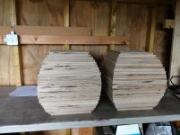
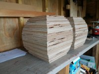
A diagonal pencil line has been drawn from opposite corners to locate the centres. These lines will aid with aligning each layer with each other. On all of the even numbered layers additional lines parallel to the edges of the squares have been drawn as these layers will be rotated by 45° relative to the adjacent layers.
A 4mm hole is drilled in the centre of each piece to act as a centre for the router jig. Two countersunk holes have been drilled near opposite corners in order to attach the squares to the base of the router jig.
Niffy
I have finished the first step in the construction. I have cut the plywood sheets into squares. Each square is 30mm larger than the disc that it is to be cut from it. The discs will be cut with a router with a 12mm straight bit. This will leave a 3mm sliver of wood at the edges which will hopefully help make the routing process easier.
There are currently 54 squares, 27 per speaker. The speakers will be made from 29 disks , the 2 smallest being cut from the centres of 2 of the larger ones. It was a tight squeeze to get all of the squares from the material available, the off cut pile is tiny. I hope I don't mess up anywhere as I don't enough wood left to make any replacement pieces. Here are the squares stacked in order.


A diagonal pencil line has been drawn from opposite corners to locate the centres. These lines will aid with aligning each layer with each other. On all of the even numbered layers additional lines parallel to the edges of the squares have been drawn as these layers will be rotated by 45° relative to the adjacent layers.
A 4mm hole is drilled in the centre of each piece to act as a centre for the router jig. Two countersunk holes have been drilled near opposite corners in order to attach the squares to the base of the router jig.
Niffy
Router jig
The first batch of disks have been cut.
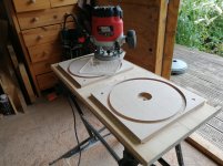
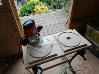
The base of the jig is offcut of furniture board with a batten of 2 by 2 glued to its underside. The batten allows the jig to be held in the Jaws of my trusty workmate. Set into the board there are two metal inserts each with a 4mm hole into which the peg from the upper part will be inserted. Metal inserts were used as a hole just made in the wood of the board would probably deform with repeated use.
The upper part of the jig is made from 8mm polycarbonate and has M4 tapped holes for each of the sizes required. The 4mm peg is fitted into one of these threaded holes.
The square from which the disk is to be cut is secured to the base with a couple of screws.
I found that making two passes with the router was easier than trying to do it in one.
The jig works really well and is much faster than I expected.
Looks like I'm going to make a lot of sawdust.
Niffy
The first batch of disks have been cut.


The base of the jig is offcut of furniture board with a batten of 2 by 2 glued to its underside. The batten allows the jig to be held in the Jaws of my trusty workmate. Set into the board there are two metal inserts each with a 4mm hole into which the peg from the upper part will be inserted. Metal inserts were used as a hole just made in the wood of the board would probably deform with repeated use.
The upper part of the jig is made from 8mm polycarbonate and has M4 tapped holes for each of the sizes required. The 4mm peg is fitted into one of these threaded holes.
The square from which the disk is to be cut is secured to the base with a couple of screws.
I found that making two passes with the router was easier than trying to do it in one.
The jig works really well and is much faster than I expected.
Looks like I'm going to make a lot of sawdust.
Niffy
On the amount of sawdust, I have a question.
Why did you choose such a wide bit? Wouldn't a 1/4" bit make for an easier cut and produce less sawdust?
Last Christmas my brother and I made a 71" lay-over extension to our round dining table (the youngsters now being old enough to bring their "honeys"). He insisted on using a 5/8" wide bit. It was a tough slog (better him than me) and it worked fine but later he observed that maybe I had been right about the 1/4" bit.
I'd appreciate your thoughts.
Hi mhenschel,
I have found that a high cutting speed works better. By doubling the bit diameter I double the speed of the cutting edge. I have also found that the groove cut by a smaller diameter tends to clog up with sawdust which can overheat the bit. Using a 1/4" bit would require more shallower cuts so would take longer overall. A 12mm bit cuts nice and easy.
I still have to sweep the same area of floor so it won't take much longer if I have to sweep up twice as much sawdust. The only advantage of a smaller radius bit is slightly less material wastage.
Niffy
A piece of plywood used in the intended orientation has shearing between each layer of veneer. The transition from one ply to the next causes an imdeance change which acts as a damping mechanism. Rotating the material to not take advantage of this leaves you with only a greater amount of material to create the damping.
dave
Hi Dave,
I've been busy with building and documentation and haven't had the chance to get back to you.
First off I completely agree that using plywood in its intended orientation is the superior option.
Ideally for the shape of cabinet that I am building I would want alternative layers to run forward/backwards and in hoops around the diameter. This is impossible to achieve building from plywood sheet. The only way to achieve this sort of layup would be by winding prepreg composite ribbon. This is way beyond my capability.
If we consider a panel of plywood. The rigidity is mainly due to tension and compression along the grain of alternate layers. Damping is due to shearing of the intermediate layers that are aligned at 90°. The shearing is parallel to the surface of the panel. The panel will be slightly stiffer aligned with the outer grain orientation due to the second moment of area being slightly greater in this direction.
With a translam panel made with horizontally stacked pieces the rigidity laterally will be similar (but less than) that of the traditional ply panel. This is because there is as much grain running left to right with a similar second moment of area. In this case the damping is also due to shearing of the intermediate layers but this time perpendicular to the surface. The rigidity vertically will be much lower. This is because there are no grains running in this direction. In this case the rigidity is not due to the tension and compression of the surface but due to shearing between the layers at 90° to the surface. This is what give translam its superior damping. The rigidity in this direction is determined not by the elastic modulus but by the shear modulus, which will be much lower.
A translam panel of similar thickness to a traditional panel with have a slightly lower stiffness laterally and similar damping. It will have much lower rigidity vertically but with higher damping.
If we double the thickness of a panel we increase its rigidity 8 fold. If we assume that the translam is almost as rigid laterally but much less rigid vertically. Doubling the thickness should result in the translam being at least as rigid overall .(assuming that the panel is securely mounted along all sides).
Hopefully my 40mm thick walls will be about as rigid as if they were 20mm traditional ply.
Niffy
Stage two complete
Well that went more smoothly than I thought it would.
I have cut all the layers for both speakers. I haven't done any of the glueing yet, I've just stacked the layers to get a feeling of how they will eventually look.
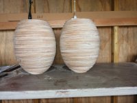
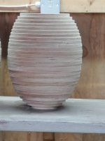
They are looking pretty good so far. They do appear to be more elongated than I pictured. I'm hoping that they will look more rounded once the steps have been sanded.
Niffy
Well that went more smoothly than I thought it would.
I have cut all the layers for both speakers. I haven't done any of the glueing yet, I've just stacked the layers to get a feeling of how they will eventually look.


They are looking pretty good so far. They do appear to be more elongated than I pictured. I'm hoping that they will look more rounded once the steps have been sanded.
Niffy
Those look pretty good.
What glue are you planning to use?
Clamping?
Sequencing (pairwise then glue glued pairs together and do on)
Please ignore if you've covered this already. (On my tiny phone and greedy)
What glue are you planning to use?
Clamping?
Sequencing (pairwise then glue glued pairs together and do on)
Please ignore if you've covered this already. (On my tiny phone and greedy)
Hi mhenschel,
I'm going to use wood glue. Initially I will be glueing the layers into five sections. The baffle section will be made of two layers. This will allow the addition of stanchions around the driver mounting hardware. The next layer, the front section will be seven layers glued together. The middle and rear sections will be nine layers each. Making the sections 7-9 layers thick with allow me sand the inside profiles. Making the sections with more layers would make sanding more difficult. Once the inner profiles are formed the sections can be glued together. I'll show the clamping in my next post when I do the glueing. Hopefully I'll get the first batch of glueing done in the next couple of days.
Niffy
All glued up
I've glued all of the disks into the sections I outlined in my previous post. I was having so much fun that I forgot to photograph the glueing of the baffle, rear and back panels. I did take a couple of pictures of the front and middle sections. The method for all the middle sections is the same so this doesn't really matter.
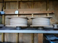
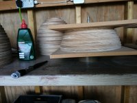
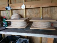
A good layer of wood glue was spread onto a disk before the next was placed on top. The disks were aligned using the pencil lines I mentioned in a previous post. Each layer being rotated by 45° relative to the previous. The disks would have had a tendency of moving around as other layers were added due to the liquid layer of glue between them. To prevent this and ensure that alignment remained fixed a couple of panel pins were hammered through each pair of layers.
The clamps are made from 300mm squares of mdf. M10 threaded bars with nuts and big washers were used to clamp the squares either side of the glued up section. I misplaced my 10mm nuts so had to use wing nuts for the first couple of sections. Hooking a spanner over the wing nut still allowed me to tighten the clamps sufficiently. Luckily I found the nuts for the last couple of sections. The baffles and back panels were clamped using G-clamps and offcuts of wood. The glueing seems to have worked very well. The sections are good and solid.
Niffy
I've glued all of the disks into the sections I outlined in my previous post. I was having so much fun that I forgot to photograph the glueing of the baffle, rear and back panels. I did take a couple of pictures of the front and middle sections. The method for all the middle sections is the same so this doesn't really matter.


A good layer of wood glue was spread onto a disk before the next was placed on top. The disks were aligned using the pencil lines I mentioned in a previous post. Each layer being rotated by 45° relative to the previous. The disks would have had a tendency of moving around as other layers were added due to the liquid layer of glue between them. To prevent this and ensure that alignment remained fixed a couple of panel pins were hammered through each pair of layers.
The clamps are made from 300mm squares of mdf. M10 threaded bars with nuts and big washers were used to clamp the squares either side of the glued up section. I misplaced my 10mm nuts so had to use wing nuts for the first couple of sections. Hooking a spanner over the wing nut still allowed me to tighten the clamps sufficiently. Luckily I found the nuts for the last couple of sections. The baffles and back panels were clamped using G-clamps and offcuts of wood. The glueing seems to have worked very well. The sections are good and solid.
Niffy
Last edited:
Internal profile
Hi all,
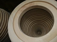
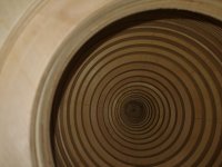
I have finished the shaping of the inside of the cabinets. To make this as easy as possible the I built a turntable that rotates the sections at about 30rpm. I can then use a flap sander attached to my drill to slowly smooth out the profile. The turntable was built mainly from my scraps bin. I also borrowed a motor and gears from my DIY record cleaning machine. This motor was from the rince cycle. The motor is mounted with a couple of bakalite plates, left over from the power supply boards of my power amps. This doubles up as the lateral bearing. The vertical load is supported on 6 ball race bearings that sit under the periphery of the turntable. These also prevent the table from tilting. These bearings were the only component that I needed to purchase for making this tool, everything else was from the scrap bin or repurposed. The sections were attached to the turntable with screws. Some of scrap left over from the centres of the disks were used as spacers.
The shaping was performed using flap sanders. These were attached to an extention rod so that they could reach the bottom of the sections. Several different sizes and grades of sanders were used. For the front section and the front of the middle section an angle grinder flap sander was also used.
The profile came out really accurately, the separate sections aligning with each other with only a tiny fraction of a millimetre error.
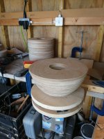
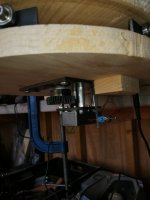
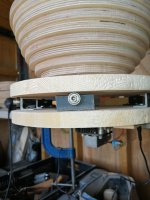
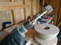
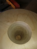
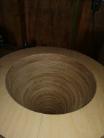
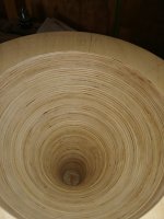
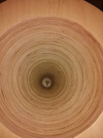
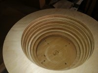
The final photo shows the front section before being profiled.
The next step will be to glue the middle and rear sections together and smooth out the joint and then varnish the inside surfaces.
Niffy
Hi all,
I have finished the shaping of the inside of the cabinets. To make this as easy as possible the I built a turntable that rotates the sections at about 30rpm. I can then use a flap sander attached to my drill to slowly smooth out the profile. The turntable was built mainly from my scraps bin. I also borrowed a motor and gears from my DIY record cleaning machine. This motor was from the rince cycle. The motor is mounted with a couple of bakalite plates, left over from the power supply boards of my power amps. This doubles up as the lateral bearing. The vertical load is supported on 6 ball race bearings that sit under the periphery of the turntable. These also prevent the table from tilting. These bearings were the only component that I needed to purchase for making this tool, everything else was from the scrap bin or repurposed. The sections were attached to the turntable with screws. Some of scrap left over from the centres of the disks were used as spacers.
The shaping was performed using flap sanders. These were attached to an extention rod so that they could reach the bottom of the sections. Several different sizes and grades of sanders were used. For the front section and the front of the middle section an angle grinder flap sander was also used.
The profile came out really accurately, the separate sections aligning with each other with only a tiny fraction of a millimetre error.


The final photo shows the front section before being profiled.
The next step will be to glue the middle and rear sections together and smooth out the joint and then varnish the inside surfaces.
Niffy
Hi Dave,
The shape of the interior is designed so that all of the sound from the back of the driver is reflected into the narrowing section at the rear of the speaker. There are no surfaces angled to reflect the sound back towards the front. The rear section is filled with wadding material that has a logarithmic increase in density towards the back acting as an absorption line.
By smoothing the surface it should act as an acoustic mirror. If I had left the surface stepped there would have had a lot of surface that could reflect back towards the front. The idea of stepping the surface in order to break up the sound wave won't work on this scale as the steps would be far too small. To be effective the steps would need to be larger than a quarter wavelength of the sound being diffracted, a 12mm step would only be really effective above 10khz.
The aim is to minimise the amount of energy from the rear of the driver that can reflect back through it into the room.
Niffy
Last edited:
Fascinating build, Niffy.
Two things:
Your design objectives for the inside configuration have "Arthur Bailey" written all over 'em. I like that. Bailey figured on transmitting the energy safely away from the rear of the cone and out; you're capturing it inside.
I remember reading an article a long time ago about a "special black" coating for solar collector surfaces that featured an array of teardrop profiles intended to do just what you are trying to do: prevent energy from reflecting back. I can't seem to find an image with the exact profile but I imagine yours might be a good approximation.
For exactly the same reason as the B&W Nautilus.Why are you smoothing the interior, it may be counter productive.
dave
- Home
- Loudspeakers
- Full Range
- Jordan Eikona Translam Ellipsoid