anatech said:A sim doesn't tell you what happens when you build something either. It only gives you an idea as long as your construction is up to par. That and in a perfect world. 😉
-Chris
Chris,
you would be surprised how much it tells. Just my experience from building real world circuits 😉 . It saves plenty of time.
Pavel
Hi Pavel,
I should really learn how to do this. I normally just design, layout and build. Then adjust values.
-Chris
I should really learn how to do this. I normally just design, layout and build. Then adjust values.
-Chris
Pavel,
Of course we appreciate your technical knowhow and skills which are a great contribution to this thread.
I just want to make a small remark that the circuit for which you posted the distortion (harmonic) plots, is not John Curl's circuit, but was posted by me, like many others have done in this thread. John has never posted any example or partial circuit as such in this thread, so logically these circuits cannot be called his.
Reverse engineering has a negative sound attached to it, but for many diy-ers it is a way of learning what makes a design unique. Many of Nelson Pass's commercial designs have been reverse-engineered on this forum for personal DIY purposes. Often Nelson gives usefull hints on improving a design, encourages and inspires many with and through his designs.
John is an experienced designer and he shares in a different and often confusing way. Perhaps not intentionally to confuse, but in a far too academic way forgetting that diy-ers of different kind of levels visit this forum to learn and improve their knowledge, insights and skills. That brings about an atmosphere of second-guessing which is of no benefit to anyone. It also brings about endless threads where important design topics are only scratched at the surface, instead of being stimulating and inspiring.

Transient Analysis Limits
Pavel, what Time Range & Maximun Time Step you are using for 1 kHz distortion analysis ?
PMA said:The proper use of simulation tools is a part of my know-how...
Pavel, what Time Range & Maximun Time Step you are using for 1 kHz distortion analysis ?
Good question. Also do not forget to ask about DSP parameters and smallest time step. Let the sine response to settle down not to analyze initial turn-on distortion.
Thanks Pavel, I thought first period(s) behavior is natural. Though different schematics have different settling times and amplitudes?PMA said:Let the sine response to settle down not to analyze initial turn-on distortion.
Of course it is natural, it is created by transfer function (BW) and it may be only linear distortion in nature, though affecting FFT result. In case we wanted to compare simulation result and result measured on the real prototype, we had to eliminate sources of confusion. We were interested in harmonic analysis, not in time domain influences. Spectral analysis always brings its specific problems - length and shape of time window etc., that influence its results.
JC wrote:
Given the output Z is 1k + some reactance and that this preamp needs to drive a cable, connectors and the non-linear input Z of the power amp it is attached to, what would you estimate the range of TOTAL distortion of a 20kHz signal to be with typical cables and amplifiers?
Ok, a tough question, but I'm interested in how you estimate it (or how JC estimates it).
Pavel, your simulation appears to show about -80dB 3rd harmonic at full output swing with no external load.PMA's simulation looks good. It looks just like what I measure.
Given the output Z is 1k + some reactance and that this preamp needs to drive a cable, connectors and the non-linear input Z of the power amp it is attached to, what would you estimate the range of TOTAL distortion of a 20kHz signal to be with typical cables and amplifiers?
Ok, a tough question, but I'm interested in how you estimate it (or how JC estimates it).
so, after all this, did anyone actually build any of the proposed line stages and regulator systems to "see" what it sounded like?
my likelihood of bumping into a blowtorch is pretty slim. i had a chance to listen to an ayre k5xe and I'm liking what i heard.
😀
mlloyd1
(who is not trying to hijack a dead thread)
my likelihood of bumping into a blowtorch is pretty slim. i had a chance to listen to an ayre k5xe and I'm liking what i heard.
😀
mlloyd1
(who is not trying to hijack a dead thread)
Hi mlloyd1,
Good question. This is a great thread despite it's earlier problems.
I for one, have a great interest in it.
-Chris
Good question. This is a great thread despite it's earlier problems.
I for one, have a great interest in it.
-Chris
Bear in mind that proposed schematics are strongly based on individual interpretations of given information in this thread.
Given the fact, that due to known reasons, the designer cannot give away his secrets, one must realize that the information is not as accurate as some (most) would like it to be. This is definately not suitable as a general DIY-project given the complexity of the overall design. Of course everyone handy enough will eventually come up with a working derative which will sound pretty good too.
Personally I think the Power supply topic could have been explored a bit more in depth without giving away any secret directly related to the BT. As every design benefits from a better (less noisier) PS, it would have stimulated DIY-ers to take their design/project a step further.
My personal experience with given information is, that it starts making sence after reading it a couple of times. Some of it puts you on a side-track leading in the wrong direction, mainly for reasons I mentioned earlier. Perseverance may however lead to a breakthrough in discovering the missing links 😀 . Until then it makes no sence in building such a design, because you will for sure run into unforseen problems easily overlooked.
Hi courage,
I'm not thinking of the thread that way at all.
One does not copy the blowtorch. It's more a learning process where I can implement some of the ideas into my existing designs, or items I own. Not completely, just an improvement.
Anything I can learn is something to be grateful for. John has shared many concepts that can be explored on the bench. I don't drive simulators. I haven't got my license yet. 😉
Discussing these gems with input from many has more value than any course I can think of. So for whatever everyone has constructively shared - thank you! No reason to stop. IP discussions can go to "the other thread".
-Chris
Hello Anatech,
I just expressed MY personal experience, not directly related to your posting. I think I'm entitled to my own opinion which does not have to be critisized and hold against that of you or others. Just let it be my opinion, or is that too much asked?
I just expressed MY personal experience, not directly related to your posting. I think I'm entitled to my own opinion which does not have to be critisized and hold against that of you or others. Just let it be my opinion, or is that too much asked?
Hi courage,
I was mostly agreeing with you. 😉
I'm glad you got something out of it also. Please understand that no criticism was intended or implied.
I think there is value in talking about the different aspects of this design. You could start a thread about how a power supply can impact the sound quality. I'm sure there is enough material.
Cheers!
just so it's clear, i was not looking to copy the blowtorch either.
i thought there were some interesting ideas and proposals exchanged in this long thread. i wanted to know if anyone tried any of them out.
mlloyd1
i thought there were some interesting ideas and proposals exchanged in this long thread. i wanted to know if anyone tried any of them out.
mlloyd1
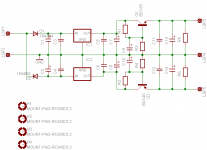
Personally, I thought that the power supply info had been covered and even more added.
The CTC supply is composed of 2 regulators for each voltage. One is a 317 or a 337, and the other is an open loop shunt regulator to capture any transient overshoot coming through the 317. The final series regulator is ALWAYS on board the specific circuit board that it regulates. Here, a cap multiplier using a mosfet power device is adequate. This is NOT a quiet regulator as the mosfet makes too much noise for that, and this final regulator is inadequate for a phono stage. I hope this this is sufficient to remove any questions.
The CTC supply is composed of 2 regulators for each voltage. One is a 317 or a 337, and the other is an open loop shunt regulator to capture any transient overshoot coming through the 317. The final series regulator is ALWAYS on board the specific circuit board that it regulates. Here, a cap multiplier using a mosfet power device is adequate. This is NOT a quiet regulator as the mosfet makes too much noise for that, and this final regulator is inadequate for a phono stage. I hope this this is sufficient to remove any questions.
John,
Thanks for your update on any info I may have missed.
Given the fact that the PS is one of the key sections in an open loop line stage and one aimes to design it as noise-free as can be, I wonder why you have choosen the last stage to be a series regulator which as you already mention is noisier, but also has a higher impedance.
Secondly what kind of PS or stage would be more suitable to use for a phono stage?
Regards.
Hi mlloyd1,
I didn't realize that was a raw nerve. What you were getting at was clearly written. I agree with you.
Guys, I'm not so subtle. I'll come out and say what's on my mind. Please accept my apologies if any of you felt I was taking a shot at you.
John,
Your experience is teaching myself and others a fair amount. Just trying to take it all in. The knowledge is added to what others bring and is definitely more than one person could experience.
Power supplies have come a long way since 7815 and 7915's. They were supposed to be perfect in the early 80's.
-Chris
- Status
- Not open for further replies.
- Home
- Amplifiers
- Solid State
- John Curl's Blowtorch preamplifier