I believe we speak about transistor biasing rather than simple diode biasing, and 2 transistors may have advantage compared to 1 transistor.
There are indeed many 'junctions' in a multi-pair output stage, 20 junctions is nothing that special.
There are indeed many 'junctions' in a multi-pair output stage, 20 junctions is nothing that special.
janneman said:If you put a cap across a relay (I assume you mean the contacts) be carefull that you never close the contacts when there is charge on the cap. Shorting a cap directly is not something those contacts will take lightly 😉
Jan Didden
Here is how I protect the speaker protection relay ( I use an LRZ)
Clamping diodes to Vcc avoids inductance induced voltage spikes on the output leads when opening so the contacts remain under 300V which is the dangerous glow arcing voltage.
Metallic arcing can happen at low voltage. They are avoided on opening by using a protection bipolar capacitor in parallel with the contacts. The capacitor value is calculated so that the voltage rate of rise on the contacts at opening remains below 1V/mìcrosec for worse case Iouput peak. This will avoid any metallic arcing at opening. At closing, the microprocessor mutes the LME49810 before switching the relay on. Therefore there is no voltage on the contacts and no arcing due to inrush current in the empty large protection capacitor. In this way, the classical serie resistor to control inrush current in the capacitor is avoided. This resistor creates a voltage drop on opening of the contact and creates then some initial spikes.
JPV
PMA, Princess and the Pea.
Is there a difference between forward biased and reverse biased junctions? Or is "junctions" this year's "steel leads"?
Is there a difference between forward biased and reverse biased junctions? Or is "junctions" this year's "steel leads"?
JPV said:
Here is how I protect the speaker protection relay ( I use an LRZ)
Clamping diodes to Vcc avoids inductance induced voltage spikes on the output leads when opening so the contacts remain under 300V which is the dangerous glow arcing voltage.
Metallic arcing can happen at low voltage. They are avoided on opening by using a protection bipolar capacitor in parallel with the contacts. The capacitor value is calculated so that the voltage rate of rise on the contacts at opening remains below 1V/mìcrosec for worse case Iouput peak. This will avoid any metallic arcing at opening. At closing, the microprocessor mutes the LME49810 before switching the relay on. Therefore there is no voltage on the contacts and no arcing due to inrush current in the empty large protection capacitor. In this way, the classical serie resistor to control inrush current in the capacitor is avoided. This resistor creates a voltage drop on opening of the contact and creates then some initial spikes.
JPV
Yes, that seems a sensible thing to do.
Jan Didden
JPV said:
Here is how I protect the speaker protection relay ( I use an LRZ)
Clamping diodes to Vcc avoids inductance induced voltage spikes on the output leads when opening so the contacts remain under 300V which is the dangerous glow arcing voltage.
Metallic arcing can happen at low voltage. They are avoided on opening by using a protection bipolar capacitor in parallel with the contacts. The capacitor value is calculated so that the voltage rate of rise on the contacts at opening remains below 1V/mìcrosec for worse case Iouput peak. This will avoid any metallic arcing at opening. At closing, the microprocessor mutes the LME49810 before switching the relay on. Therefore there is no voltage on the contacts and no arcing due to inrush current in the empty large protection capacitor. In this way, the classical serie resistor to control inrush current in the capacitor is avoided. This resistor creates a voltage drop on opening of the contact and creates then some initial spikes.
JPV
A uproc in an amp?
Won't that generate and radiate noise?
(Tice clock anyone?)
Do we want such a thing?
Do we not want to capacitively couple the output if we are only worried (so much) about DC destroying a speaker?
What about the cap holding a charge as the amp turns on, and then the contacts close?
Btw, if you attached an image, I don't see it...

Do all the amps that you folks run and buy create big thumps on turn on/ turn off??
_-_-bear
We use output relays with Parasound power amps. I have little to do with its control or protection. In a perfect world, I would not use relays at all. Most of my custom designs do not use any relay, except for fuse replacement.
bear said:
A uproc in an amp?
Won't that generate and radiate noise?
(Tice clock anyone?)
Do we want such a thing?
Do we not want to capacitively couple the output if we are only worried (so much) about DC destroying a speaker?
What about the cap holding a charge as the amp turns on, and then the contacts close?
Btw, if you attached an image, I don't see it...
Do all the amps that you folks run and buy create big thumps on turn on/ turn off??
_-_-bear
In my system a microprocessor supervises 5 amps remotely. The alarms and supervision signals are opto coupled and if necessary EMI filtered to the clean ground so there is NO emi entering in the audio system.
If this has to be done for a normal amp mono or stereo you can do it easly with non clocked discrete logic so no noise.
The muting of the amplifier puts the ouput of the amp at zero volt before turning on therefore no charges remaining on the protective capacitor because the load is at zero volt too
JPV
Hi Jan,
The relay I referred to is going to be a speaker relay. A small foil type of something around 0.1 uF is placed across the N.O. contacts. The idea of this is to preserve some of the detail that might be conceivably be lost due to the contact. It may even help to quench a small arc as the contacts open.
This is just an idea that may help over time.
What would be helpful for speaker relay protection would be a small signal relay at the input that normally shorts the input signal to ground. This would be timed so that the sound is muted until after the main contacts close and before they open on fault or turn off. That should next to eliminate the small arcing that raises the contact resistance over time. Just a nice touch.
-Chris
The relay I referred to is going to be a speaker relay. A small foil type of something around 0.1 uF is placed across the N.O. contacts. The idea of this is to preserve some of the detail that might be conceivably be lost due to the contact. It may even help to quench a small arc as the contacts open.
This is just an idea that may help over time.
Not in line with the speaker output are they? That creates double the connections across contacts, never mind that fuses would be a non-linear resistance that blows your damping factor out of the water. Of course, you could include the fuse inside your feedback loop if this is what you are talking about.Most of my custom designs do not use any relay, except for fuse replacement.
What would be helpful for speaker relay protection would be a small signal relay at the input that normally shorts the input signal to ground. This would be timed so that the sound is muted until after the main contacts close and before they open on fault or turn off. That should next to eliminate the small arcing that raises the contact resistance over time. Just a nice touch.
-Chris
I use circuit breakers only in the power supply. Nowhere else, if I can help it. Parasound amps need relays, and it is a traditional part of the design.
Chris,
I'm not sure about that cap. What would the effect be of 0.1uF across 0.01 ohms contact resistance?
But it still can damage the contact when it closes at the wrong moment (and in this business ALL moments are usually wrong 😉 ).
Jan
I'm not sure about that cap. What would the effect be of 0.1uF across 0.01 ohms contact resistance?
But it still can damage the contact when it closes at the wrong moment (and in this business ALL moments are usually wrong 😉 ).
Jan
anatech said:Hi Jan,
The relay I referred to is going to be a speaker relay. A small foil type of something around 0.1 uF is placed across the N.O. contacts. The idea of this is to preserve some of the detail that might be conceivably be lost due to the contact. It may even help to quench a small arc as the contacts open.
This is just an idea that may help over time.
Not in line with the speaker output are they? That creates double the connections across contacts, never mind that fuses would be a non-linear resistance that blows your damping factor out of the water. Of course, you could include the fuse inside your feedback loop if this is what you are talking about.
What would be helpful for speaker relay protection would be a small signal relay at the input that normally shorts the input signal to ground. This would be timed so that the sound is muted until after the main contacts close and before they open on fault or turn off. That should next to eliminate the small arcing that raises the contact resistance over time. Just a nice touch.
-Chris
Muting the input of the amp before switching on the relay is what I am using. In this way the capacitor is empty and sees no voltage before switch on and there is no inrush current.
Why would you not use a large correctly calculated bipolar capacitor to suppress the arc at switch off. I beleive that avoiding contact wear is the most important issue there.
JPV
On the risk that people think I have stock in Amplomo 😉 :
I have repeatedly mentioned their special speaker relay. It has a 100A rated tungsten contact that closes first, then this is bridged by a gold or silver (don't remember) contact. On opening, the sequence is in reverse.
Worth a try.
Jan Didden
I have repeatedly mentioned their special speaker relay. It has a 100A rated tungsten contact that closes first, then this is bridged by a gold or silver (don't remember) contact. On opening, the sequence is in reverse.
Worth a try.
Jan Didden
janneman said:On the risk that people think I have stock in Amplomo 😉 :
I have repeatedly mentioned their special speaker relay. It has a 100A rated tungsten contact that closes first, then this is bridged by a gold or silver (don't remember) contact. On opening, the sequence is in reverse.
Worth a try.
Jan Didden
This is the great contact a try to protect of course.
I still have a question. Let suppose you have a perfect contact protection without any arcing. What is the influence of environmental corrosion ( it is a silver gold coated contact). Is it not then better to have some arcing, but that is really not controllable.
JPV
You mean corrosion by the environment / air borne pollutants? I think you should make sure you have a hermetically closed relay.
Jan Didden
Jan Didden
janneman said:You mean corrosion by the environment / air borne pollutants? I think you should make sure you have a hermetically closed relay.
Jan Didden
Is the amplimo LRZ hermetically close ?
JPV
Hi,
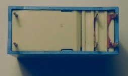
The Amplimo LRZ relays I have are a different pattern from those in Edmond's picture, but they are certainly not hermetically sealed.
There is no sealant around the tags, and anyway, as with all such relays I use, I popped one open to inspect the internals.
The Amplimo LRZ relays I have are a different pattern from those in Edmond's picture, but they are certainly not hermetically sealed.
There is no sealant around the tags, and anyway, as with all such relays I use, I popped one open to inspect the internals.
No they are not hermetically sealed, true. You could mount it with a gasket between the relay and board, if you wanted, I guess. The solder pads should be airtight.
BTW Do you guys re-seat your interlinks and speaker connectors every few weeks to clean them? That is where the money is. That is also why often things sound different when you changed cables: you just cleaned your connector contacts 😉 .
Jan Didden
BTW Do you guys re-seat your interlinks and speaker connectors every few weeks to clean them? That is where the money is. That is also why often things sound different when you changed cables: you just cleaned your connector contacts 😉 .
Jan Didden
- Status
- Not open for further replies.
- Home
- Amplifiers
- Solid State
- John Curl's Blowtorch preamplifier