>Jfet input stages have no significant advantage
>in this regard over bjt input stages emitter
>degenerated to a similar gm.
The advantage is that the junction on the
jfet is reversed biased.
The junction on the bjt is forward biased.
(sorta like a regenerative am demodulator)
Overcoming reversedness is harder than
abbetting forwardness.
>in this regard over bjt input stages emitter
>degenerated to a similar gm.
The advantage is that the junction on the
jfet is reversed biased.
The junction on the bjt is forward biased.
(sorta like a regenerative am demodulator)
Overcoming reversedness is harder than
abbetting forwardness.
hitsware said:>Jfet input stages have no significant advantage
>in this regard over bjt input stages emitter
>degenerated to a similar gm.
The advantage is that the junction on the
jfet is reversed biased.
The junction on the bjt is forward biased.
I am aware of that. But the b-e junction needs to be reverse biased to some degree by the RF voltage before the BJT can behave as an adequate detector.
If the BJT input stage is heavily emitter degenerated (for other reasons such as linearity, particularly as OLG< with >frequency, lower gm / <Ccomp / >slew rate / <TIM, etc) it's immunity to AM demodulation is increased significantly as a much larger RF input voltage is required to overload it.
For stray RF voltages (especially signals in the AM broadcast frequency range), that do not cause overload, the input stage itself will just amplify them pretty much linearly along with the audio input signal.
Cheers,
Glen
Has everyone understood that bipolar transistors tend to rectify RF, because they are already conducting? However, jfets are have a completely turned off diode in normal operation. It is a higher barrier to cross, before RF rectification can happen.
Of course, I am speculating that this is so, but I will stand corrected by higher authority, if there is a better explanation.
Of course, I am speculating that this is so, but I will stand corrected by higher authority, if there is a better explanation.
G.Kleinschmidt said:
That is not true and a complete misrepresentation:
http://www.dself.dsl.pipex.com/ampins/dipa/dipa.htm
I speak about the book, chapter 4, not this short webpage analysis. Anyway, good to see his web result:
An externally hosted image should be here but it was not working when we last tested it.
and compare with mine. Input stage of this kind is really not appreciated.
PMA said:
I speak about the book, chapter 4, not this short webpage analysis. Anyway, good to see his web result:
and compare with mine. Input stage of this kind is really not appreciated.
Good grief. Your blanket claim was a plain misrepresentation of what he has published and that graph that you cite is for a BJT long tail pair without emitter degeneration and with a very low tail current, as shown in figure 6 (reproduced below)
This is far from the final input stage used in the "Blameless" amplifier (you only have to glance at the rest of that webpage) and the experiment was conducted to show the effects of the percentage of Ie imbalance on the LTP linearity.
An externally hosted image should be here but it was not working when we last tested it.
john curl said:This is not the Doug Self thread. Why are we discussing this?
We are discussing and making comparisons about input stages. Part of that D.Self webpage is explicitly concerned with input stages.
This is pointless, it has been discussed in a biased way by Doug Self, himself. He doesn't even use fets for anything that I know of.
G.Kleinschmidt said:
I am aware of that. But the b-e junction needs to be reverse biased to some degree by the RF voltage before the BJT can behave as an adequate detector.
If the BJT input stage is heavily emitter degenerated (for other reasons such as linearity, particularly as OLG< with >frequency, lower gm / <Ccomp / >slew rate / <TIM, etc) it's immunity to AM demodulation is increased significantly as a much larger RF input voltage is required to overload it.
For stray RF voltages (especially signals in the AM broadcast frequency range), that do not cause overload, the input stage itself will just amplify them pretty much linearly along with the audio input signal.
Cheers,
Glen
Glen,
I agree that a degenerated BJT stage is not good as an AM detector. AM detection needs a nonlinear device to generate the 0 (signal) and 2w (to be filtered) harmonics. The more linear the stage, the less effective this process is.
Now, comparing BJTs and JFETs is not really straightforward; BJTs could easily be driven in the exponential Ic-Vbe region (which extends over many decades of current) by simply by keeping the device non-degenerated and perhaps low DC biased. Of course, a strongly biased BJT with strong emitter degeneration will be very linear, and hence a really poor AM detector. But so is a JFET stage, biased around Idss with source degeneration. In these regions, under large signal conditions, Ic and Id are still slightly exponential and parabolic dependent on Vbe and Vgs, and perhaps unless you compare a very poor BJT (Having a very low exponentil m factor) with a high gain 2SK170 JFET, the bipolar will still be a more efficient AM detector.
Now, if you bias the JFET closer to Vt (that is, e.g. by increasing the source resistor degeneration in an non LTP stage), the AM detection efficiency of the JFET will increase considerably! This is completely opposite to the bipolar behaviour and the reason is that by approaching the threshold voltage the JFET enters the subthreshold conduction region. In this region Id-Vgs is as exponential as the BJT, turning the JFET in an effective AM detector.
You see, unlikely a BJT, for non LTP stages, by increasing the source degeneration of a depletion JFET you are in fact increasing its AM demodulation efficiency. From this perspective, it would be fair to compare BJTs and MOSFET AM detection efficiencies and of course the MOSFET would win. But MOSFETs can be barely used as input stages...
One to another, if you compare a BJT LTP degenerated stage with a JFET LTP degenerated stage, biased around Idss, and the input signal is relatively small, the bipolar stage will be more efficient in detecting AM signals. If the input signal increases, then the JFET can reach the subthreshold region and could become as effective in AM detection as the BJT.
john curl said:This is pointless, it has been discussed in a biased way by Doug Self, himself. He doesn't even use fets for anything that I know of.
Hello John
The reason he does not use a fets is due the fact that you need a matched input pair it work with the LTP, wheras with a BJT input you can use unmatched parts and it will work fine provided you use a current mirror with them . Secondly matched Jfets are harder to get these days.
Regards
Arthur
syn08 said:
Glen,
I agree that a degenerated BJT stage is not good as an AM detector. AM detection needs a nonlinear device to generate the 0 (signal) and 2w (to be filtered) harmonics. The more linear the stage, the less effective this process is.
Now, comparing BJTs and JFETs is not really straightforward; BJTs could easily be driven in the exponential Ic-Vbe region (which extends over many decades of current) by simply by keeping the device non-degenerated and perhaps low DC biased. Of course, a strongly biased BJT with strong emitter degeneration will be very linear, and hence a really poor AM detector. But so is a JFET stage, biased around Idss with source degeneration. In these regions, under large signal conditions, Ic and Id are still slightly exponential and parabolic dependent on Vbe and Vgs, and perhaps unless you compare a very poor BJT (Having a very low exponentil m factor) with a high gain 2SK170 JFET, the bipolar will still be a more efficient AM detector.
Now, if you bias the JFET closer to Vt (that is, e.g. by increasing the source resistor degeneration in an non LTP stage), the AM detection efficiency of the JFET will increase considerably! This is completely opposite to the bipolar behaviour and the reason is that by approaching the threshold voltage the JFET enters the subthreshold conduction region. In this region Id-Vgs is as exponential as the BJT, turning the JFET in an effective AM detector.
You see, unlikely a BJT, for non LTP stages, by increasing the source degeneration of a depletion JFET you are in fact increasing its AM demodulation efficiency. From this perspective, it would be fair to compare BJTs and MOSFET AM detection efficiencies and of course the MOSFET would win. But MOSFETs can be barely used as input stages...
One to another, if you compare a BJT LTP degenerated stage with a JFET LTP degenerated stage, biased around Idss, and the input signal is relatively small, the bipolar stage will be more efficient in detecting AM signals. If the input signal increases, then the JFET can reach the subthreshold region and could become as effective in AM detection as the BJT.
Hi
I agree with all these points. However my stance is that a BJT LTP emitter degenerated (say to the level used in a typical amplifier such as the "blameless" or similar) is such a bad AM demodulator for low level RF that one doesn’t need to use jfet input stages to avoid the potential problem.
WRT AM detection, it should be said that one shouldn't only examine the behaviour of the input stage.
Suppose the input stage is subjected to a little low level RF from a local AM broadcast station. ~500kHz to 1600kHz signals are well with in the linear signal handling frequency limits of just about any half decent BJT or JFET input stage.
Suppose that this RF signal isn’t enough to overload the input stage. Depending entirely on the amplifier design, the input stage may quite happily amplify this RF signal and pass it onto the following stage where it may have even more potential to cause problems.
Back in my teenage years I found this out the hard way, running my mono amplifier circuit from a partially dismembered record player housed in a wooden box, offering zippo RF shielding. A signal from a local AM station induced in this (and possibly also in my zip cord input lead) was being demodulated by my amplifier and annoying me through the speaker.
The amp used a degenerated BJT long tail pair with a single resistive load, driving a single un-degenerated PNP VAS. The closed loop gain was high and frequency compensation was achieved with a shunt capacitor from the VAS collector to ground.
Well, you can almost guess which stage was doing the demodulation. I found that the little bit of RF was causing no trouble with the BJT LTP, but it was being amplified and detected by the VAS. (if you think about it, a VAS like this is almost set up to be a rectifier when overloaded).
I fixed the problem by alternatively compensating the amplifier by connecting a sexy greencap capacitor (several nf from memory) directly across the LTP load resistor. That killed the RF gain of the LTP, removed the RF signal from the VAS base and no more inane Bob Francis talk-back rants intruded on my Spandau Ballet tunes – just lots of mains hum 🙂
Cheers,
Glen
PHEONIX said:
Hello John
The reason he does not use a fets is due the fact that you need a matched input pair it work with the LTP, wheras with a BJT input you can use unmatched parts and it will work fine provided you use a current mirror with them . Secondly matched Jfets are harder to get these days.
Regards
Arthur
No, as explained on his website with ample substantiation, be doesn't use JFETs for the long tail pair because BJT's emitter degenerated to the same gm simply have far better linearity.
Cheers,
Glen
G.Kleinschmidt said:
No, as explained on his website with ample substantiation, be doesn't use JFETs for the long tail pair because BJT's emitter degenerated to the same gm simply have far better linearity.
Cheers,
Glen
My stance on this is pretty simple: for a LTP input stage, using JFETs is not really a big deal (I like the high input impedance, though). However, you can build with matched complementary JFETs a really nice non-LTP input stage. Which one (BJT LTP vs. symmetrical non-LTP JFET) is better in terms of distortions it's hard to say, it's not an apple-apple comparison. Theoretically, the JFET stage is better, but then the complementary JFET availability and JFET matching requirements brings this approach to the "not for new development" stage.
The advantage is that the junction on the
jfet is reversed biased.
The junction on the bjt is forward biased.
(sorta like a regenerative am demodulator)
Overcoming reversedness is harder than
abbetting forwardness.
No, it only changes the optimum source impedance
for the, say -10 dBm of Rf pump energy to produce
maximum damage.
More on diode power matching is in Maas' book on
diode microwave mixers.
regards, Gerhard
john curl said:Has everyone understood that bipolar transistors tend to rectify RF, because they are already conducting? However, jfets are have a completely turned off diode in normal operation. It is a higher barrier to cross, before RF rectification can happen.
Of course, I am speculating that this is so, but I will stand corrected by higher authority, if there is a better explanation.
So what, JFETs are conducting already, too. It doesn't take a diode
to rectify. Any nonlinearity will do. In fact, they use power FETs as
rectifiers for low voltages/high currents when even Schottky diodes
have too large a Vf.
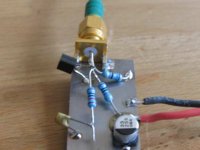
Ten minutes demo of a rectifying JFET with parts that happen to be
on the table:
-6 dbm / 100mV eff at 4 MHz , amplitude modulated to 99 % from a
Rohde & Schwarz SMPD signal generator.
Attachments
Ooohps, have problems to include multiple pictures.
Output after the mild low pass:
(this is not a simulation, picture is from Agilent Infiniium scope
with 2.25 GHz BW that has a web server to get the screen shots..)
The FET not only rectifies, it has conversion gain!
How much RF power does it take to produce 100 mV into 15 pF,
w/o the (50) 47 Ohm resistor?
Yellow: gate voltage, 0V is in the middle of the lower half of the picture
Green: drain voltage after 1 pole RC low pass.
Attachments
Well, does anyone want to know how to make fet based amplifier circuits? The Blowtorch is virtually 100% complementary fet. So is the Vendetta Research phono stage, and the Parasound JC-2 preamp, along with most of my more modern designs. Doug Self has his own website, and well he stocks it, but it is only one design approach, and I have been debating Doug Self in print since 1984, on circuit design philosopy. Do you know that he did not believe, at one time that caps, were anything less the perfect? DA was a joke, and connectors etc should be a cheap as you can find to use. What does this approach have to do with the design goals set on this thread?
john curl said:What does this approach have to do with the design goals set on this thread?
Indeed nothing. But anything related preamps and input stages, regardless of the origin of design has merit to be discussed. One never knows what new or brilliant ideas might surface.
/Hugo
...........up early Mr.Curl?
Would you care about commenting about the use of bipolars for the folded cascode portion of the blowtorch. It might not be as elegant but matching should be simpler and easier for most diyer's to construct.........we are not talking about absolutes here but what pitfalls we may face and compromises in performance.
Regards,
Jam
- Status
- Not open for further replies.
- Home
- Amplifiers
- Solid State
- John Curl's Blowtorch preamplifier