john curl said:Start explaining, Glen.
I'll give you a hint: The input pair(s) will not have a demodulation effect until any (typically non-common mode) RF input signal overloads it.
Emitter degenerated BJT amplifier stages are more than capable of linearly amplifying high level amplitude modulated RF carriers without demodulating them:
http://users.picknowl.com.au/~glenk/K160AM.HTM
Not fair?
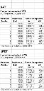
With both arrangments, I have a "gm" in R1 or R11 of 3.75mS (=3.75mA per 1V input swing), and this is fair enough I think. This Gm I use to mirror the current and this will result in the same OLG.
But I have changed the arrangement:
R2 - R5 = 150 Ohm
R6 - R9 = 750 Ohm
For the same current swing, I had to set R1 = 100 Ohm.
These are the results:
G.Kleinschmidt said:This isn't a fair comparison because the 10 ohms emitter degeneration is nowhere near enough to bring the BJT gm down to that of the jfet gm. The optimal "bridge" resistor (R1, R11) will be far from the same in each case also.
With both arrangments, I have a "gm" in R1 or R11 of 3.75mS (=3.75mA per 1V input swing), and this is fair enough I think. This Gm I use to mirror the current and this will result in the same OLG.
But I have changed the arrangement:
R2 - R5 = 150 Ohm
R6 - R9 = 750 Ohm
For the same current swing, I had to set R1 = 100 Ohm.
These are the results:
Attachments
Re: Not fair?
Hi Zinsula,
So you are testing the circuits with a 1V input swing. Isn't that far, far too much? Under normal operating conditions, the differential input voltage is far less. Could you also look at the distortion figures at 0.1V input, please?
Cheers.
zinsula said:With both arrangments, I have a "gm" in R1 or R11 of 3.75mS (=3.75mA per 1V input swing), and this is fair enough I think.
Hi Zinsula,
So you are testing the circuits with a 1V input swing. Isn't that far, far too much? Under normal operating conditions, the differential input voltage is far less. Could you also look at the distortion figures at 0.1V input, please?
Cheers.
Re: Re: Not fair?
Differential input voltage, or preamp input voltage? Under "normal operating conditions" the input voltage at preamp input terminals is up to 2.5Vrms SE from CD player output, twice from balanced output.
Edmond Stuart said:
Hi Zinsula,
So you are testing the circuits with a 1V input swing. Isn't that far, far too much? Under normal operating conditions, the differential input voltage is far less. Could you also look at the distortion figures at 0.1V input, please?
Cheers.
Differential input voltage, or preamp input voltage? Under "normal operating conditions" the input voltage at preamp input terminals is up to 2.5Vrms SE from CD player output, twice from balanced output.
Re: Re: Not fair?
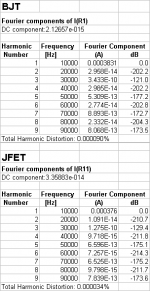
Well, I am thinking about "open loop line stage".
But of course, if feedback is applied...
Here is the same config. as above, but 0.1V input swing.
Tino
Edmond Stuart said:
Hi Zinsula,
So you are testing the circuits with a 1V input swing. Isn't that far, far too much? Under normal operating conditions, the differential input voltage is far less. Could you also look at the distortion figures at 0.1V input, please?
Cheers.
Well, I am thinking about "open loop line stage".
But of course, if feedback is applied...
Here is the same config. as above, but 0.1V input swing.
Tino
Attachments
That's also the case with Douglas Self's analysis of "Small signal stages". He shows distortion of the whole amplifier, no one knows at what output amplitude, no one knows what is input voltage, no one knows distortion of the isolated input stage. And, analysis by 1 frequency sine tone is not very interesting, especially in case of high NFB design with low-frequency OLG roll-off, where differential voltage rises proportionally to signal frequency, pushing the input stage to less linear portion of transfer function. I want for my design to respond properly to input step with non-limited rise time, i.e. to some 5-10ns. Properly I mean not to get slew-rate limited.
Pavel, of course my simulations only show one frequency (10kHz), I fear I'm not able to perform more sophisticated tests.
It was one of my first trials at distortion simulation....
I did it more for myself, trying to see some difference between BJT and JFET.
At least, I believe I have isolated enough the input stage.
Tino
It was one of my first trials at distortion simulation....
I did it more for myself, trying to see some difference between BJT and JFET.
At least, I believe I have isolated enough the input stage.
Tino
Tino, my post was not adressed to your simulation. It was adressed to the previous requirement to reduce input voltage.
PMA said:Tino, my post was not adressed to your simulation.
Ah, sorry, it's OK anyway.
I wish to point out that not all is yet lost in fet design. There are many fets that are available, even if they might not have the extra low noise of the discontinued Toshiba devices.
The problem is not impossible for amateurs, but professionals who want to make lots of something and need 100's to 1000's of p channel parts today in order to make an individual design have a problem. After all, anyone can get some parts for their personal hi fi project through Erno B, as he has limited stocks left. Isn't your time and effort worth something also?
Why cheapen it, with cheap, compromised parts?
The examples of quality bipolar design are many, and even I had a 5 year interval when I developed my best topologies, where complementary fets were virtually non-existant, and I designed everything with complementary bipolar transistors.
Complementary jfets do have some unique advantages, however, and I will continue to exploit them.
PMA said:That's also the case with Douglas Self's analysis of "Small signal stages". He shows distortion of the whole amplifier, no one knows at what output amplitude, no one knows what is input voltage, no one knows distortion of the isolated input stage.
[snip]
You don't know this, you don't know that, you don't know etc.
Use your simulator (you have a nice one btw) and you will know. 😀
Pavel & Tino,
Are you proving that JFETs produce less distortion than BJTs?
If that's the case, then I'm not convinced.
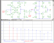
The circuits below convinced me of the opposite.
They were operating at almost the same conditions.
Io = 2mApk-pk
JFET: THD20=479ppm (blue)
BJT: THD20 = 36ppm (red)
Cheers.
Are you proving that JFETs produce less distortion than BJTs?
If that's the case, then I'm not convinced.
The circuits below convinced me of the opposite.
They were operating at almost the same conditions.
Io = 2mApk-pk
JFET: THD20=479ppm (blue)
BJT: THD20 = 36ppm (red)
Cheers.
Attachments
Yesterday Barrie Gilbert showed me how to extend the James Schmook gm flattener to +-300mV of distortionless input range. Amazing. 
Edmond Stuart said:Pavel & Tino,
Are you proving that JFETs produce less distortion than BJTs?
If that's the case, then I'm not convinced.
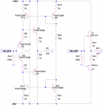
I'm only showing what I got. Nothing to "prove".
An I tried to compare same topologies.
Your BJT topology should be compared with a similar JFET topology.
See attached schematic.
Attachments

another entry in the "degenerated bjt are more linear than jfets" sim-for-all:
the above is at sub-audio frequencies to remove device C effects, but the principle should still apply at HF, and the smaller junction area of bjt give better gain vs parasitic C ratio than jfets
if you want the Ltspice file:
http://www.diyaudio.com/forums/showthread.php?postid=501789#post501789
jcx said:returning to input diff pair distortions (really, really consider starting new threads, this thread is way unwieldy with just input stage distortion discussion going on)
To illustrate the some points about the relative gain/distortion tradeoffs of bjt vs fet diff pair inputs I’ve simulated a perfectly linear model amp with a un/degenerated bjt diff pair vs a fet diff pair input
In this sim I am trying to eliminate everything except diff pair input stage gm nonlinearity, the current mirror (V2, F1) nearly eliminates 2nd order nonlinearity, to exclude dynamic nonlinearity from bjt/fet nonlinear junction C I scaled frequency down, feedback impedance is low to eliminate base current effects
With the current mirror the gain intercept for this sim is 436 Hz for the bjt diff pair (closed loop gain = +14, GBW = 14 * 432 Hz = 6.1 KHz, just scale up frequencies by ~1-2K and C1 down by the same ratio to get back to typical audio amp numbers)
The test signal is a 10 Hz sine, amplitude modulated with a 1 Hz sine (“unbalanced” to preserve the carrier this time ‘round) – BTW, I believe this would be a good sim approach to Gilbert’s analysis, similar GBW ratio, slightly more gain and the amplitude of the test signal is “automatically” swept by the AM modulation – no need for andy_c’s math sw skills, anyone competent to seriously modify or design their own audio amps should be able to use spice at this level, feel free to modify and examine whatever phase/IMD ratio you want in (free) Lt Spice
The first fft is an “unfair” comparison, just dropping in fets in place of the bjts isn’t a clear distortion win (the unfairness comes from the loop gain reduction with lower fet gm)
The second fft evens up the loop gain/GBW by decreasing C1 for the fet input circuit, now the fet looks pretty good – but I maintain this is still an unfair comparison, we just added nearly 20 dB loop gain to make up for the fet’s low gm
A final, more even-handed comparison adds 210 Ohm degeneration Rs to the bjt emitters which lowers the diff pair stage gm to the same level as the fet input while providing local linearizing feedback, and adds the same loop gain to both by setting C1=C2= 110n
Note that to even see any higher order distortion in the degenerated bjt stage I’ve extended the dB scale down to -160 dB (a tiny spot of green shows @ -160 dB, 50Hz - the fifth harmonic)
I think this shows you need to consider device gain, local and global feedback together to evaluate the roles of nonlinearity vs gain, bjts have more gain (when gm is the important parameter) than fets, enough more gain that local feedback linearization can give better distortion results with the bjt devices at equivalent gm
the above is at sub-audio frequencies to remove device C effects, but the principle should still apply at HF, and the smaller junction area of bjt give better gain vs parasitic C ratio than jfets
if you want the Ltspice file:
http://www.diyaudio.com/forums/showthread.php?postid=501789#post501789
- Status
- Not open for further replies.
- Home
- Amplifiers
- Solid State
- John Curl's Blowtorch preamplifier