>Others feel that they are more tolerant of EMI effects.
For sure. The forward bias on bipolar devices
makes for a am demodulator.
I once sold some ic preamps to a store
(auditioned in the store)
After I delivered the units suddenly they all hummed
through the phono section.
I switched out the NE5534 for TL071 and they were
cured.
An early Comcast tower had been fired up in the
neighborhood. Strange how the 60Hz rode on the
RF 🙂
john curl said:What are you referring to, Terry?
WRT Edmonds front end measurement or mine?
hitsware said:>Others feel that they are more tolerant of EMI effects.
For sure. The forward bias on bipolar devices
makes for a am demodulator.
I once sold some ic preamps to a store
(auditioned in the store)
After I delivered the units suddenly they all hummed
through the phono section.
I switched out the NE5534 for TL071 and they were
cured.
Only if they are biased near cut off - which is typical in many packaged opamps which do not use emitter degeneration for the input LTP.
Jfet input stages have no significant advantage in this regard over bjt input stages emitter degenerated to a similar gm.
john curl said:I am confused as to what is being addressed.
OK. Edmond has developed a new front end for, I presume, a new
power amp. He has given distortion figures (simulated?) for the
front end in isolation.
My question is; how do you accurately isolate the linearity of the front
end of a power amp that uses global FB in a meaningful way?
Since the back end of the amp is part of the front ends load, etc.
cheers
Terry
Edmond Stuart said:
Indeed, it's a beautiful thing, but where to get them nowadays (in quantity and in the future)? That's why I'm forced to use an arrangement with BJTs plus the inevitable and evil current sources.
Or ones that are sufficiently complementary so that the simulation results produced here are reproducible in real life.
Differential/symmetrical circuits with jfets with miraculously low THD figures are easy to produce in simulation, as the distortion produced by the jfets consists of even harmonics, and even harmonics cancel out in differential/symmetrical circuits.
However that assumes that the nonlinearity of the n channel parts accurately complements the p channel parts.
WRT amplifier noise, it is useless to consider the effects of only the input stage when using low gm devices such as jfets for input stages. Without a high impedance drain load the gain will be low and then the noise contribution of the following stage (typically the VAS) will contribute to a greater degree. BJT’s with their much higher gm are ahead in this regard.
Cheers,
Glen
john curl said:You are incorrect, Glen.
🙄 No I am not incorrect. The demodulation mechanism is so basic it is hardly worth explaining.
Edmond Stuart said:
Hi Bob,
I'm perfectly happy with BJTs. I know that certain jfets produce slightly less noise (courtesy of John Curl), but do we really need them in the input stage of a power amp, where noise is less of a concern?
Do jfets produce less distortion? Maybe, but still I don't need them for my power amp. My latest front-end does ~50ppb distortion at 20kHz. Will those who think that's too much, stand up.
Cheers,
Edmond.
BTW, even with the demise of complementary dual n and p jfets, we are not doomed to only use LTP’s for fully complementary input stages with BJT’s.
See here:
http://users.picknowl.com.au/~glenk/K800ABVA.GIF
Or alternatively the pic below 😀
Cheers,
Glen
Attachments
hitsware said:
The forward bias on bipolar devices
makes for a am demodulator.
I switched out the NE5534 for TL071 and they were
cured.
This is true, regarding RF demodulation. Experienced and verified, I exchanged NE5532s for OPA2134s for the same reason.
Also, in my new opamp test method, I found many BJT input opamps sensitive to FM pilot and TV row freq. Namely LME49710, NE5534. The only well-behaving BJT input opamps were AD797 and LT1028, from those I have tested.
On the other hand, no problem with OPA627, OPA134, AD744, AD825. All JFET input opamps.
Also, fast CFB BJT AD844 behaved perfectly.
G.Kleinschmidt said:BTW, even with the demise of complementary dual n and p jfets, we are not doomed to only use LTP’s for fully complementary input stages with BJT’s.
See here:
http://users.picknowl.com.au/~glenk/K800ABVA.GIF
Or alternatively the pic below 😀
Cheers,
Glen
G.Kleinschmidt said:WRT amplifier noise, it is useless to consider the effects of only the input stage when using low gm devices such as jfets for input stages. Without a high impedance drain load the gain will be low and then the noise contribution of the following stage (typically the VAS) will contribute to a greater degree. BJT’s with their much higher gm are ahead in this regard.
Cheers,
Glen
Hi Glen.
Agreed. One more reason not to use jfets. Another reason is that, at least in my application, jfets produce twice as much distortion.
So I'm using something like one half of circuit as shown in your h.gif. It's a CFB input stage, configured as diamond buffer.
BTW, I assume that it is just as immune for HF interference as the AD844 (also a CFB amp).
Cheers,
Edmond.
zinsula said:Of course, such a complementary input differential can be done with BJT's...you just need a whole bunch of more parts.
As in the example here.
Does somone recognize this schematic? No, it's not a one million dollar question 😉
Tino
Apparently you don't know the difference between an input stage and a complete amp or op-amp. 😀
My IPS contains a 'bunch' of only six trannies, current sources included.
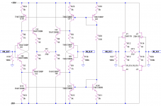
Yesterday evening, I have compared the following BJT (left) and JFET (right) differential stages.
R1 respectively R11 set to get same current swing with same input voltage (around 3.7mA/Volt).
This current could be mirrored to the transconductance node in the next stage, eg. as in the AD844.
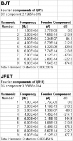
In the next post, the simulated distortions.
R1 respectively R11 set to get same current swing with same input voltage (around 3.7mA/Volt).
This current could be mirrored to the transconductance node in the next stage, eg. as in the AD844.
In the next post, the simulated distortions.
Attachments
Thank you for the reminder.Edmond Stuart said:
Apparently you don't know the difference between an input stage and a complete amp or op-amp. 😀
OK. And for balanced (the BT is balanced, for instance) you'd need 12, isn't it?Edmond Stuart said:My IPS contains a 'bunch' of only six trannies, current sources included.
Zinsula,
Okay that is a bunch of BJTs, but it's far from representative of a common CFB input stage.
Okay that is a bunch of BJTs, but it's far from representative of a common CFB input stage.
zinsula said:Thank you for the reminder.
OK. And for balanced (the BT is balanced, for instance) you'd need 12, isn't it?
My circuit is already balanced, as it is complementary. It is pointless to double balance this circuit. Ask Bob Cordell. 😀
Moreover my IPS (a CFB thingy) is faster, i.e. less phase shift in the FB loop and equally important, it is suitable for DTMC in order to increase the phase margin of the FB loop even more.
zinsula said:Yesterday evening, I have compared the following BJT (left) and JFET (right) differential stages.
R1 respectively R11 set to get same current swing with same input voltage (around 3.7mA/Volt).
This current could be mirrored to the transconductance node in the next stage, eg. as in the AD844.
In the next post, the simulated distortions.
This isn't a fair comparison because the 10 ohms emitter degeneration is nowhere near enough to bring the BJT gm down to that of the jfet gm. The optimal "bridge" resistor (R1, R11) will be far from the same in each case also.
- Status
- Not open for further replies.
- Home
- Amplifiers
- Solid State
- John Curl's Blowtorch preamplifier