Just to illustrate a few points I made in a previous post about the ability of emitter degenerated BJT input stages to pass relatively large RF voltages linearly and the fact that RF overload and AM demodulation can happen in stages after the input stage before the input stage actually causes a problem, I have run a quick sim of the basic amplifier I described earlier (post 7031).
The LTspice schematic appears below. The original circuit had a complementary Darlington emitter follower output stage, but for simulation purposes I just used a VCVS.
Please note that this does not represent a “HiFi” design, but the principles are applicable to amplifiers of far greater complexity and I think are rather important with respect to the potential problem of AM demodulation.
Attachments
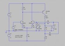
The design has an emitter degenerated BJT long tail pair input stage with a tail current of only 630uA.
Note that this is a rather low tail current which, even with the 220 ohm emitter degeneration resistors, does not give this input stage very high signal handling capabilities.
For this simulation I applied a 600kHz sinewave of 150mV peak to the input of the amplifier. 600kHz is at the lower end of the AM broadcast band and 150mV peak represents quite a major case of RF infection.
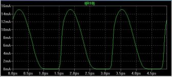
Attached below is a plot of the complementary emitter currents of the long tail pair BJTs. As can be seen, the input signal of 150mV peak is not enough to cause overload or a degree of non-linearity for effective AM demodulation. There is a bit of visible distortion, but that can be expected at a frequency of 600kHz with such a low tail current.
This simulation of these emitter currents was done with the inverting input grounded as it is necessary to isolate the LTP from the massively distorted signal produced by the VAS (see next post) to properly inspect the input stage linearity.
Note that this is a rather low tail current which, even with the 220 ohm emitter degeneration resistors, does not give this input stage very high signal handling capabilities.
For this simulation I applied a 600kHz sinewave of 150mV peak to the input of the amplifier. 600kHz is at the lower end of the AM broadcast band and 150mV peak represents quite a major case of RF infection.
Attached below is a plot of the complementary emitter currents of the long tail pair BJTs. As can be seen, the input signal of 150mV peak is not enough to cause overload or a degree of non-linearity for effective AM demodulation. There is a bit of visible distortion, but that can be expected at a frequency of 600kHz with such a low tail current.
This simulation of these emitter currents was done with the inverting input grounded as it is necessary to isolate the LTP from the massively distorted signal produced by the VAS (see next post) to properly inspect the input stage linearity.
Attachments

And lastly, here is a plot of the collector current of the VAS clearly showing a half wave rectified sinewave making it clear that AM demodulation will happen here well before it does in the input stage.
The simulation of the VAS current was of course done with the negative feedback connection to the inverting input restored.
To summarise:
The input long tail pair is responding in a linear fashion to a high level RF input signal without overload.
This RF input signal, further amplified by the long tail pair, is causing overload of the following stage – in this case the VAS.
A single ended VAS such as this when overdriven has the capability of conducting far in excess of two times the quiescent current, as a consequence of which, a crude rectification of high level input signals takes place.
The most important point to make at the end of this is that, with the same value (220 ohms) emitter degeneration resistors, a BJT input stage of a more refined amplifier supplied with a tail current of, say, 5mA, will have vastly improved frequency response, improved linearity and an overload margin almost TEN times higher than the one presented here.
Attachments
G.Kleinschmidt said:[snip]
To summarise:
The input long tail pair is responding in a linear fashion to a high level RF input signal without overload.
This RF input signal, further amplified by the long tail pair, is causing overload of the following stage – in this case VAS.
A single ended VAS such as this when overdriven has the capability of conducting far in excess of two times the quiescent current, as a consequence of which, a crude rectification of high level input signals takes place.
[snip
Hi Glen,
Okay, it's the single ended VAS, being the greatest culprit. So I wonder to what extent a fully complementary front-end will rectify HF interference. Perhaps you can simulate this too (I can't do it at the moment, as I'm not at home now) and perhaps you'll find one more reason to use a complementary VAS. 😀
Cheers,
Edmond.
G.Kleinschmidt said:
Hi Bob.
I have no argument that a non-emitter degenerated BJT LTP can work as excellent AM detector (especially if Ie is reasonable, decreasing re and increasing the gain), as only a very small non-common mode AM RF signal is required to overload it.
But to repeat what I wrote in my first post on this topic (specifically referring to the input stage):
Jfet input stages have no significant advantage in this regard over bjt input stages emitter degenerated to a similar gm.
This statement isn't general, but quite specific. I think that any advantage a jfet input stage under these conditions may have over bjt input stage isn’t significant because if you have enough stray RF voltage to overload the input stage (reverse bias the b-e junctions) you’ve got other problems to worry about.
And generally, non degenerated BJT input stages are far from optimal for other reasons besides RF detection.
It does get boring when someone claims that a simple statement like the one above is wrong, and then to prove it, argues for a point that isn't under contention.
Cheers,
Glen
Hi Glen,
There is a lot of truth to what you are saying. In fairness to your points, it is true that many BJT op amps do not employ emitter degeneration, and that accounts for a lot of what is being said in the context of BJT vs JFET op amps. It is certainly true that degeneration of the BJT input LTP greatly reduces RF susceptibility and, of course, has many other really important advantages.
I do believe that there are some conditions under which the P-N base-emitter junction of a BJT being exposed to RF can lead to some rectification effects even when degenerated. This could be the case, for example, when there are stray capacitances and inductances at the base and emitter nodes and the device is exposed to fairly high frequencies, perhaps like the rampant spectral pollution that exists in the 2.4 GHz band these days. Resonances and antenna effects in discrete circuits can occur at high frequencies. The fact that even a few mV that gets between the base and emitter by hook or by crook is the source of concern.
One useful test is to operate a cell phone in very close proximity to your circuit. If noting comes through, that may be an indication that you are in pretty good shape.
Cheers,
Bob
Edmond Stuart said:
Hi Glen,
Okay, it's the single ended VAS, being the greatest culprit. So I wonder to what extent a fully complementary front-end will rectify HF interference. Perhaps you can simulate this too (I can't do it at the moment, as I'm not at home now) and perhaps you'll find one more reason to use a complementary VAS. 😀
Cheers,
Edmond.
Hi Edmond.
Unfortunately it is 1am here so I should probably go to bed.
BTW, the single ended VAS is much better behaved if you use miller compensation, as this turns the VAS into an integrator which effectively kills the HF gain right where it matters.
I think a differential VAS will only be better in so far as it can maintain balance when over driven with a high frequency signal. Also, again, like in the singe ended VAS topology, it depends very much on how the amplifier is frequency compensated.
Cheers,
Glen
Bob Cordell said:
I do believe that there are some conditions under which the P-N base-emitter junction of a BJT being exposed to RF can lead to some rectification effects even when degenerated. This could be the case, for example, when there are stray capacitances and inductances at the base and emitter nodes and the device is exposed to fairly high frequencies, perhaps like the rampant spectral pollution that exists in the 2.4 GHz band these days. Resonances and antenna effects in discrete circuits can occur at high frequencies. The fact that even a few mV that gets between the base and emitter by hook or by crook is the source of concern.
One useful test is to operate a cell phone in very close proximity to your circuit. If noting comes through, that may be an indication that you are in pretty good shape.
Cheers,
Bob
Hi Bob.
I agree in theory, but is is the AM broadcast band signals I think that are of greatest concern as these fall not very far out of the pass band of an amplifiers input filter.
Not sure though how much of the VHF, UHF, etc stuff is prone to get into an amplifier that is adequately shielded.
Cheers,
Glen
john curl said:Well, does anyone want to know how to make fet based amplifier circuits? ...
i do, i do! 🙂
back to fets ...
john, i was looking over the PLD-2000. looks like that's your handiwork also, correct?
any pearls you could share about that design since it's a discontinued product?
mlloyd1
>That killed the RF gain of the LTP,
>removed the RF signal from the VAS
>base and no more inane Bob Francis
>talk-back rants intruded on my Spandau
>Ballet tunes – just lots of mains hum
Then you may not have killed the radio,
but only retuned it.
The RF pickup problems I have had
(IC phono sections) have manifested
as mains hum. I don't know the mechanism
of broadcast (AC powerlines modulating
RF carriers?, light dimmers?, ??) but again,
switching to jfet input ICs fixed it.
apples and oranges
Opposed to structures based on LTPs, a CFB (or push pull) input stage has to be different, because BJT's vs JFETs are so different. IOW, you can't compare BJTs vs JFETs using the same topology. Therefore I have chosen for a comparison based on equal numbers of active devices in the signal path (hence only one half) and equal drain/collector currents. I think that's fair.
You are right, the impedance of the inverting input is very low. If this input is used for (global) NFB, not a problem at all.
Two such circuits? It depends on your application. Agreed, the DC balance is rather poor, also the individual signals from the 'top' and 'bottom' output is more or less distorted. However, if these two signals are summed together, the distortion can be very low.
Cheers.
PMA said:Well - you are right. But they are really different structures, we compared BJT and JFET differential input stage, your CFB has almost zero -input impedance, and structure is well known and explored - and very good, agreed.
Opposed to structures based on LTPs, a CFB (or push pull) input stage has to be different, because BJT's vs JFETs are so different. IOW, you can't compare BJTs vs JFETs using the same topology. Therefore I have chosen for a comparison based on equal numbers of active devices in the signal path (hence only one half) and equal drain/collector currents. I think that's fair.
You are right, the impedance of the inverting input is very low. If this input is used for (global) NFB, not a problem at all.
PMA said:The case is that that CFB circuit is not well applied as a balanced, you should use 2 such circuits.
Two such circuits? It depends on your application. Agreed, the DC balance is rather poor, also the individual signals from the 'top' and 'bottom' output is more or less distorted. However, if these two signals are summed together, the distortion can be very low.
Cheers.
There is a section in the Analog Device book " OP Amp Applications" by Walt Jung, 2002, that is titled "Input-stage RFI rectification sensitivity". In it Walt goes on to show that JFETs are less sensitive to RFI that bipolar transistors. Some of the points made are:
BJT input devices rectify readly due to their forward-biased B-E junction and they have exponential I-V transfer characteristics
FET input devices are less sensitive to rectifying due to their reversed-biased p-n junction and their square-law I-V transfer characteristics.
Please see pages 7.122 - 7.125 for further information on why JFETs are less sensitive to RFI rectification than bipolars.
Thanks Rick, for your input. I forgot that reference.
Did you find the link? If not, email me through your regular email and I will send it to you.
Did you find the link? If not, email me through your regular email and I will send it to you.
Hi John
Just a quick question, why are jfets never used in second stages of amps?? Couple of weeks back Scott Wurcer showed an opamp in another thread that used jfets in the second stage, i was amazed, pretty good perormance too.
I agree with mlloyd, why not start a permanent amplifier thread, i think we could all learn a thing or two from it too. I know theres a lot of bickering but most of us have learnt a great deal from this thread and would appreciate your input concerning power amps. Well, actually the bickering brings out the best in people, the experienced members go through a lot of trouble to prove their points and the ones like me reading in between the lines find a wealth of knowledge there.
Thanks for the input you have already given in this thread.
Alex
I use them in second stages, but there is a problem with max voltage swing with jfets. Look at a p ch spec sheet on the 2sj74 and your answer will be there. Mos fets are noisy.
Hi,
Are Szikai pairs in single (Mike Renardson's amplifier) or differential LTP schemes used in input stages more susceptible to rectifying effects than single devices ?
Are Szikai pairs in single (Mike Renardson's amplifier) or differential LTP schemes used in input stages more susceptible to rectifying effects than single devices ?
john curl said:I use them in second stages, but there is a problem with max voltage swing with jfets. Look at a p ch spec sheet on the 2sj74 and your answer will be there. Mos fets are noisy.
Another gem/clue, Thank you.
http://www.analog.com/library/analogdialogue/archives/39-05/Web_Ch7_final_J.pdfjohn curl said:Thanks Rick, for your input. I forgot that reference.
Did you find the link? If not, email me through your regular email and I will send it to you.
I recall a Gordon Instruments MicPre talk/demo where it was claimed all of the V gain is done with jfets and they were special order factory screened for ~ 2x their nominal V rating
http://www.gordonaudio.com/index.htm
I don't recall any discussion of noise, apparently "high V" for a preamp @ pro level +30 dBm output with fets in the 2nd stage works for some people?
although I do understand that for low noise jfet input stages may not want too much V
http://www.gordonaudio.com/index.htm
I don't recall any discussion of noise, apparently "high V" for a preamp @ pro level +30 dBm output with fets in the 2nd stage works for some people?
although I do understand that for low noise jfet input stages may not want too much V
scott wurcer said:These guys have some dangerously bad goobledegook on their web site.
yes, BAS meetings/field trips are often amusing
the efforts of the Professional Audio Design guys to replicate soupcan sized output xfmrs (large due to DC bias) and find "authentic" 2N3055 to drive them in restored Neve mixing consoles was more good entertainment - who would have thought there was a demand for "period" tantalum electros in the signal path?
- Status
- Not open for further replies.
- Home
- Amplifiers
- Solid State
- John Curl's Blowtorch preamplifier