I would think that by page 192 of the Blowtorch thread it's apparent that John prefers lower feedback. Whether that means all the way to zero is an open question, but I'd say that he'd be more receptive to that idea than many.
Clearly John can and does design circuits with higher amount of feedback, but I'd venture that THX is a large part of the impetus.
Grey
Clearly John can and does design circuits with higher amount of feedback, but I'd venture that THX is a large part of the impetus.
Grey
If i had to be forced into anything i'd rather do drugs, but why do serious audio fools voluntarily go for something with an Ultra sticker ?
(at a $4k entry level you'd figure they are serious)
(at a $4k entry level you'd figure they are serious)
On jfet followers
Hi all!
Have been following this thread on and off with great interest, mostly. Thanx John for sharing your thoughts with us on this forum! I have been using a preamp built around jfet followers for about two years and I have not come up with anything to better it yet. It is sort of a bastard since it is using a transformer to give me the gain I want. The way it is built up is first a 100k ladder type attenuator followed by a complementary jfet follower with a twist followed by a 1:4 transformer topped off with yet another complementary jfet follower with the same twist. The twist is that the follower is built up like a cascode where the "upper" devices are modulated by the output to keep the voltage swing over the actual buffer as low as possible. It is all done without any servos and it is very stable. I have come to the conclusion over the years that jfet´s always sound better if they don't have to swing any or very little voltage, maybe because the capacitances are so voltage dependent.
BR,
Anders
GRollins said:I would think that by page 192 of the Blowtorch thread it's apparent that John prefers lower feedback. Whether that means all the way to zero is an open question, but I'd say that he'd be more receptive to that idea than many.
Clearly John can and does design circuits with higher amount of feedback, but I'd venture that THX is a large part of the impetus.
Grey
For audio I feel one can dispense with feedback all together. As I said Friday you can easily design complimentary circuits whose distortion mimics that of the primary audio tranducers phono, microphone, and speakers but at at least a order of magnitude lower level. I would think an argument for what little the electronics contributes being masked is easy to make.
The power amp is a problem without brutal class A. 25W amps at 1000W standby does not appeal to me.
Re: On jfet followers
I thought I posted an open-loop JFET buffer here last year that was also current modulated because it was for a known load (50K stepped attenuator) that had "0" distortion?
bappe said:Hi all!
Have been following this thread on and off with great interest, mostly. Thanx John for sharing your thoughts with us on this forum! I have been using a preamp built around jfet followers for about two years and I have not come up with anything to better it yet. It is sort of a bastard since it is using a transformer to give me the gain I want. The way it is built up is first a 100k ladder type attenuator followed by a complementary jfet follower with a twist followed by a 1:4 transformer topped off with yet another complementary jfet follower with the same twist. The twist is that the follower is built up like a cascode where the "upper" devices are modulated by the output to keep the voltage swing over the actual buffer as low as possible. It is all done without any servos and it is very stable. I have come to the conclusion over the years that jfet´s always sound better if they don't have to swing any or very little voltage, maybe because the capacitances are so voltage dependent.
BR,
Anders
I thought I posted an open-loop JFET buffer here last year that was also current modulated because it was for a known load (50K stepped attenuator) that had "0" distortion?
John another question, what are your preferred balanced in phono stages? The Grado's always seem to have hum issues in my arm and since they are 400 Ohms self noise I don't need .4nV.
BTW one of our other amplifier designers probably has a setup more to your liking. He ended up with Dennison's air bearing arm in (I forgot which) air bearing table and all Classé electronics (no op-amps). He built an industrial compressed air system in his garage and ran a high pressure air line to his listening room.
I do have guy who used to be a tech who also loves Walt's 745 phono stage. Which reminded me I designed a phono stage with the 745 using the trick of feeding back to the null pins (open looping it). We considered it unpublishable and too uncommercial.
Scott, I use single ended input, because it is inherently quieter with a given number of devices. My input noise is: 0.4nV/rt Hz +cartridge resistance noise. This is difficult to do with balanced or differential input, because as you know, the inputs are in noise series and it always adds 3dB to the noise, as well as doubling the parts. I have never had any real trouble with hum.
P.S. Sorry Scott, I misread your question, and my answer is somewhat redundant to your original message. However, I am not a grounding expert, so I too, take my chances in grounding. I don't actually see where it would make much difference between balanced and unbalanced at 400 ohms. Perhaps you should attack the SOURCE of the hum with shielding or better placement of wires or power transformers.
On further reflection, why not make an input stage from your AD524 instrumentation OP amp or some variation? That works really well with common mode rejection. Thanks again for those devices, 25 years ago or so. They really saved Walt Jung and me from a lot of hassle. How about a lower noise version with extended bandwidth and slew rate? #1 in my book.
scott wurcer said:
The power amp is a problem without brutal class A. 25W amps at 1000W standby does not appeal to me.
Scott,
Speaking solely in terms of the GR-25, the big change in distortion came with increasing the bias in the driver/2nd stage, not the output stage. The reason I biased the output so heavily is because I'm driving an unusually low resistance [sic] load and wanted class A (nearly) to the bitter end. You could easily halve the bias without doing undue violence to the measured distortion. The voltage across the output MOSFETs would be of more importance than the current/device.
Class A outputs approach, what?, 50% efficiency? Yes, that's rough, but it need not be as bad as 1kW/25W out.
The 2nd stage in the GR-25 runs at 100mA with 35V rails--i.e. 14W for all four quadrants, total. That's pretty heavy compared to other amps, but it's not that much wattage in the greater scheme of things.
Preamps and such need not be so heavily biased, obviously. The load is much tamer.
Grey
GRollins said:
Scott,
Speaking solely in terms of the GR-25, the big change in distortion came with increasing the bias in the driver/2nd stage, not the output stage. The reason I biased the output so heavily is because I'm driving an unusually low resistance [sic] load and wanted class A (nearly) to the bitter end. You could easily halve the bias without doing undue violence to the measured distortion. The voltage across the output MOSFETs would be of more importance than the current/device.
Class A outputs approach, what?, 50% efficiency? Yes, that's rough, but it need not be as bad as 1kW/25W out.
The 2nd stage in the GR-25 runs at 100mA with 35V rails--i.e. 14W for all four quadrants, total. That's pretty heavy compared to other amps, but it's not that much wattage in the greater scheme of things.
Preamps and such need not be so heavily biased, obviously. The load is much tamer.
Grey
I was thinking on my memory of the original Zen articles with the single diff-pair and drain loads. I ran my old Hafler 220 at about 50W a side.
Scott,
You want brutal? Build a Ver. 1.0 Son of Zen. Now, that's a power hog.
(We now return you to your regularly scheduled Blowtorch.)
Grey
You want brutal? Build a Ver. 1.0 Son of Zen. Now, that's a power hog.
(We now return you to your regularly scheduled Blowtorch.)
Grey
Re: Re: On jfet followers
I looked for it, but did not see it. Can you point me to it?
scott wurcer said:I thought I posted an open-loop JFET buffer here last year that was also current modulated because it was for a known load (50K stepped attenuator) that had "0" distortion?
I looked for it, but did not see it. Can you point me to it?
You guys, who like 50k pots, please tell me why do you fight for lownoise preamps and the add 15nV/sqrtHz by pot. Thanks.
PMA said:You guys, who like 50k pots, please tell me why do you fight for lownoise preamps and the add 15nV/sqrtHz by pot.
It's much less, reduced to the input. No sane engineer would place a pot at the low noise preamp input. Think S/N ratio.
PMA said:You guys, who like 50k pots, please tell me why do you fight for lownoise preamps and the add 15nV/sqrtHz by pot. Thanks.
One also wonders why anyone would want a low noise line stage. Thinking back to the input you have at least 40dB or so of RTI gain by this point so 15 nV is really .15nV RTI. At this point 15 nV from your pot translates into 300nV across the speaker terminals with a standard 26dB gain power amp. That's about 42uV rms or 5dB SPL on a 100dB/1W efficient speaker. The National Park Service surveyed noise pollution and found the absolutely quietest places in the US were about 7dB SPL.
Hi Scott,
With a 4 Ohm ultra high efficiency speaker (110dB/W) I get a SPL of 27dB at 10cm, clearly audible.
With a 4 Ohm ultra high efficiency speaker (110dB/W) I get a SPL of 27dB at 10cm, clearly audible.
Re: Re: Re: On jfet followers
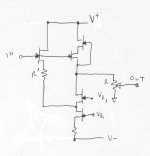
It seems it was longer ago than I remember. Here it is again. I look at it as an open loop inverting path and non-inverting path joined. In simulation you can tweek R prime to get 4ppm linearity at +-5V out on 15V rails with a 10k pot. This is clearly pushing the point.
Nelson Pass said:
I looked for it, but did not see it. Can you point me to it?
It seems it was longer ago than I remember. Here it is again. I look at it as an open loop inverting path and non-inverting path joined. In simulation you can tweek R prime to get 4ppm linearity at +-5V out on 15V rails with a 10k pot. This is clearly pushing the point.
Attachments
The National Park Service surveyed noise pollution and found the absolutely quietest places in the US were about 7dB SPL.
I would like more details if possible. How its measured is important to know. But its a very low number, much lower than I have measured in well made listening rooms. Actually lower than usually possible even with 1" microphones. A quick check of the B&K documents indicates a noise floor of 9.5 to 10 dBA for a 1" mike.
It also suggests that recordings reproduced anywhere near realistic levels will have intrinsic noise much higher than the reproducing chain if good practices are maintained.
The arguments about hearing into the noise will surface here but even if the noise is inaudible under any conventional measurements there is no reason not to keep the noise down if it doesn't compromise any other aspect. And designing for low noise is really the starting point, you can't go back and reduce the noise after the design is done without changing everything.
- Status
- Not open for further replies.
- Home
- Amplifiers
- Solid State
- John Curl's Blowtorch preamplifier