Re: Re: Neutralization
- Klaus
May I ask if it works along the lines of the impedance transform, that is putting the right thing into the base drive to get an emitter impedance without the inductive component and especially without the FDNR component?Charles Hansen said:This technique is *not* what I use to stabilize my amplifiers when driving a capacitive load. Rather it was a "jumping off" point that inspired a different circuit that worked quite well. (And if one were to see the schematic, *nobody* would claim it was a form of feedback, positive or negative.)
- Klaus
Re: Re: Re: Neutralization
That's a good question, but I don't know the answer.
When I first ran into the problem (BJT emitter followers being inherently unstable with a capacitive load), I looked in the books I had. Some of them mentioned the problem, but didn't have much useful information and certainly no solution. (My previous work with solid-state circuits had all been with FETs, which do not suffer from this problem.)
The next step was to go the local university library and see what they had. One textbook had a 2-page derivation of the math that I couldn't follow, but also had no practical solutions. None of the other books had anything useful either.
The next thing I did was call every solid-state designer I know to ask them what they knew. I started with John Curl, who knew about the problem and its cause (FDNR = Frequency Dependent Negative Resistance) and suggested putting a real and positive resistance in series with the base. I tried that, but without real success. By the time that the real resistance was large enough to have a beneficial effect, it was also increasing the output impedance of the circuit significantly. None of the other designers had much that was of any use, at least to me. (I was using an emitter-follower triple with no output inductor.) Most people told me that it couldn't be done and just use the inductor.
One book said that the most complete treatment was in Feucht's book. That was unavailable, so I got the CD-ROM version from his website. This contained enough information to get me thinking in a different direction. Then I remembered the neutralization trick from the old ARRL Handbook. I never actually built that circuit, but instead did a bunch of thought experiments and came up with a different idea that did the trick.
I don't know exactly how it works, partly because I still don't understand how an emitter follower (with a gain of less than one) can oscillate in the first place. But I suppose that you are probably right, that it somehow performs an "impedance transform" to cancel the FDNR. But I wouldn't swear to it.
And like everything else, to get the circuit to sound its best requires (guess what?) -- listening tests. But building an emitter-follower that is stable into capacitive loads without using an output inductor is definitely possible. Like I said, it took me over a month of full-time work. But maybe someone else out there is more clever and can come up with a solution more quickly.
KSTR said:May I ask if it works along the lines of the impedance transform, that is putting the right thing into the base drive to get an emitter impedance without the inductive component and especially without the FDNR component?
That's a good question, but I don't know the answer.
When I first ran into the problem (BJT emitter followers being inherently unstable with a capacitive load), I looked in the books I had. Some of them mentioned the problem, but didn't have much useful information and certainly no solution. (My previous work with solid-state circuits had all been with FETs, which do not suffer from this problem.)
The next step was to go the local university library and see what they had. One textbook had a 2-page derivation of the math that I couldn't follow, but also had no practical solutions. None of the other books had anything useful either.
The next thing I did was call every solid-state designer I know to ask them what they knew. I started with John Curl, who knew about the problem and its cause (FDNR = Frequency Dependent Negative Resistance) and suggested putting a real and positive resistance in series with the base. I tried that, but without real success. By the time that the real resistance was large enough to have a beneficial effect, it was also increasing the output impedance of the circuit significantly. None of the other designers had much that was of any use, at least to me. (I was using an emitter-follower triple with no output inductor.) Most people told me that it couldn't be done and just use the inductor.
One book said that the most complete treatment was in Feucht's book. That was unavailable, so I got the CD-ROM version from his website. This contained enough information to get me thinking in a different direction. Then I remembered the neutralization trick from the old ARRL Handbook. I never actually built that circuit, but instead did a bunch of thought experiments and came up with a different idea that did the trick.
I don't know exactly how it works, partly because I still don't understand how an emitter follower (with a gain of less than one) can oscillate in the first place. But I suppose that you are probably right, that it somehow performs an "impedance transform" to cancel the FDNR. But I wouldn't swear to it.
And like everything else, to get the circuit to sound its best requires (guess what?) -- listening tests. But building an emitter-follower that is stable into capacitive loads without using an output inductor is definitely possible. Like I said, it took me over a month of full-time work. But maybe someone else out there is more clever and can come up with a solution more quickly.
GRollins said:And there are six capacitors in that schematic, not just two.
Not sure what your point is. The circuit is an RF power amplifier, probably for use as a transmitter. The two capacitors at the output transformer (air-core, no doubt!) are just to tune the circuit for maximum gain at the operating frequency. The two caps on the filament are to provide a low impedance path for the current through the cathodes (in this case the cathodes are identically the filaments).
So the only "unusual" part of the circuit are the neutralization capacitors. Again, they cancel the Miller capacitance and extend the effective bandwidth of the particular tube. This allows more gain at the operating frequency of the power amp.
In low-level applications (ie, not power amps) another way to do this was with "peaking" coils placed in series with the plate load resistor. Look at the schematic for any tube-based Tek 'scope and you will see plenty of these.
the neutralization trick
What are they?neutralization capacitors
Thanks Mr Hansen,
for this detailed and informative reply.
I have three .PDF's of D.L.Feucht on this topic (as published in AnalogZone) which I'll need to read again, though I seem to recall that in the first one he showed exactly the R//C in the base that I mentioned (pulling it from the german standard text which also is quite complete on these matters).
Klaus
KSTR said:I have three .PDF's of D.L.Feucht on this topic (as published in AnalogZone) which I'll need to read again, though I seem to recall that in the first one he showed exactly the R//C in the base that I mentioned (pulling it from the german standard text which also is quite complete on these matters).
I have Tietze and Schenk, and it is one of my primary references. (I am still waiting for the second edition to be translated into English.) I don't recall what it said (I am at home and the book is at work), but whatever it was certainly didn't lead me directly to a solution. I wish it had, it would have saved me a month of hard work!
Can you post a scan of the R//C solution you are referring to?
Charles Hansen said:
I have Tietze and Schenk, and it is one of my primary references. (I am still waiting for the second edition to be translated into English.)
Curiously, Amazon seems to have trouble getting it in, but others under the USED & NEW hyperlink claim to have it. The publisher indicated it would be out 3/31 if I recall correctly, so it is possible that the other folks do indeed have it in stock. The publisher, Springer, also claims to be "temporarily out of stock."
Grey
Intersting discussion here about emitter followers oscillating. I also experienced this and can vouch for the fact that a stable triple without an output inductor is a rare and wonderful beast indeed. In my case, I did use an output inductor (2uH), preceded by a zobel network and then, between the pre-driver and the middle driver, inserted a 27 Ohm resistor in series to the 2nd driver transistor base with a 1nF cap to ground on each half of the output stage. I have seen some circuits where they returned the cap to ground by tying it to the plus and minus rails (assumption on this approach that this is an AC short to ground via the local decoupling caps and th e main filter caps).
This approach works well for me and finally cured the tendency for the output stage to break into HF oscillation on the -ve and occassionaly positive peaks when driving the amp quite hard (Fo in the 1-2 MHz range)
Microcap had an intersting paper on this topic and I managed to replicate their findings using LTC spice, which led me to the RC network solution.
Bonsai said:[snip]
Microcap had an intersting paper on this topic and I managed to replicate their findings using LTC spice, which led me to the RC network solution.
Hi Bonsai,
Was it published in "Spectrum News" If so, which edition?
Else, do you have a link?
Cheers,
Edmond.
HighEnd is about design as well, and we have a Blowtorch case here.
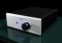
Let me input with my 12 cents. A friend of mine, professional designer, has designed a case for my headphone amplifier PCB. There will be only one unique piece produced, see the photo.
Let me input with my 12 cents. A friend of mine, professional designer, has designed a case for my headphone amplifier PCB. There will be only one unique piece produced, see the photo.
Attachments
Edmond, yes it was in their news letter.
I am travelling this week (Left coast - SJ) on business, but when I get back to Tokyo I'll get it off my hard drive and send it to you.
I am travelling this week (Left coast - SJ) on business, but when I get back to Tokyo I'll get it off my hard drive and send it to you.
BTW, I found that the MJE340/350 in the pre-driver position were very difficult to tame wrt to oscillation - especially the 350. Maybe someone with greater insight can explain this . . . . but I guess it needs to be in a more appropriate thread sinc e this one is about the blowtorch right?
Charles -
do you know the German title of the Tietze and Schenk book you are referring to (I am pretty fluent in German)?
Thanks.
Sigurd
do you know the German title of the Tietze and Schenk book you are referring to (I am pretty fluent in German)?
Thanks.
Sigurd
Charles Hansen said:
I have Tietze and Schenk, and it is one of my primary references. (I am still waiting for the second edition to be translated into English.) I don't recall what it said (I am at home and the book is at work), but whatever it was certainly didn't lead me directly to a solution. I wish it had, it would have saved me a month of hard work!
Can you post a scan of the R//C solution you are referring to?
Bonsai said:Edmond, yes it was in their news letter.
I am travelling this week (Left coast - SJ) on business, but when I get back to Tokyo I'll get it off my hard drive and send it to you.
Hi Bonsai,
I'm perfectly happy if you just tell me which edition. No need to send me News Letter itself. Thanks.
Cheers,
Edmond.
@Sigurd Ruschkow: there's only one Tietze/Schenk, it's called 'Halbleiter - Schaltungstechnik' - a pretty mean bible. I think in english it's called ' Electronic Circuits'. I have the current edition at home and would not recommend it, since the analog part is rather short (shorter than in previous editions I was told).
@Grey
Oh my god, that's was just a joke! Sorry if it was not easy to get, but I thought my post about spice-difficulties (including funny results) would make that clear.
In fact I do not simulate for my pleasure, but to get facts which I cannot get otherwise. Mainly stability prediction.
@Scott
This is so amazing. Really impressive.
I want to say it again, I really don't question the spice-concept! I fully agree, solving the equations by hand must give identical results. Solving arbitrarily large dimensioned matrices is really something for computers, actually the reason why they were developed.
However the quality of results I've got so far, tells me to take care. Since I don't question the spice-concept, it must be the device models. And I understand that many models were simply derived from datasheets or taken from manufacturers (I was told OnSemi's models are famous for being inaccurate).
Please don't forget, I'm talking about software which I can access. I fully understand that a huge IC company has their own proprietary software packages, models and probably a whole software department keeping the package at the leading edge.
Thank you!!
All the best, Hannes
@Grey
By all means, if if makes you happy to simulate the GR-25, then do so
Oh my god, that's was just a joke! Sorry if it was not easy to get, but I thought my post about spice-difficulties (including funny results) would make that clear.
In fact I do not simulate for my pleasure, but to get facts which I cannot get otherwise. Mainly stability prediction.
@Scott
And yes people still can’t believe this, you can design a ~100 or so transistor diff A/D driver with -80dB of distortion at >100MHz< and have the silicon results lay right on the simulations.
This is so amazing. Really impressive.
I want to say it again, I really don't question the spice-concept! I fully agree, solving the equations by hand must give identical results. Solving arbitrarily large dimensioned matrices is really something for computers, actually the reason why they were developed.
However the quality of results I've got so far, tells me to take care. Since I don't question the spice-concept, it must be the device models. And I understand that many models were simply derived from datasheets or taken from manufacturers (I was told OnSemi's models are famous for being inaccurate).
Please don't forget, I'm talking about software which I can access. I fully understand that a huge IC company has their own proprietary software packages, models and probably a whole software department keeping the package at the leading edge.
Best of luck Hannes
Thank you!!
All the best, Hannes
GRollins said:I'm not sure I follow how the term feedback applies to something at the same stage of amplification. There's no "back" to it.
Grey
What am I missing? You take the output signal of a gain stage and apply it back through some kind of network to the input. How could this not be called feedback?
To the best of my limited knowledge, the first formal documented application of feedback was by Bell Labs. The trans-Atlantic telephone cables had so much loss (remember, they were an all straight analog environment) that a large number of amplifiers (200?) were needed in the cable. The cumulative error of this concept was so high that the voice quality suffered from both intelligibility and gain variation issues. Bell Labs used feedback to reduce distortion and to make the unit to unit gain variations more dependent on a resistor ratio rather than relying on vacuum tube matching.
Those amplifiers had a single triode stage and the fix was called feedback. There may be a patent, somewhere around 1910-1920. My point is that I think the term "feedback" was initially defined as a single stage phenomena.
Re: Re: Re: Re: Neutralization
Yes, impedance gyration is the commonly accepted model for the emitter follower (with capacitive load) oscillator. Here's an extended discussion:
http://www.analogzone.com/col_1017.pdf
Edit: Oooops, the reference was already quoted above.
Charles Hansen said:
I don't know exactly how it works, partly because I still don't understand how an emitter follower (with a gain of less than one) can oscillate in the first place. But I suppose that you are probably right, that it somehow performs an "impedance transform" to cancel the FDNR. But I wouldn't swear to it.
Yes, impedance gyration is the commonly accepted model for the emitter follower (with capacitive load) oscillator. Here's an extended discussion:
http://www.analogzone.com/col_1017.pdf
Edit: Oooops, the reference was already quoted above.
- Status
- Not open for further replies.
- Home
- Amplifiers
- Solid State
- John Curl's Blowtorch preamplifier