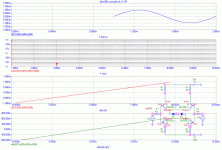
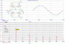
PMA, it looks good, but can't a battery be put into that spot with some reasonable voltage? It would be more ideal, but the diode is pretty good, Maybe in reality, a large current Shottky diode for lowest V drop might actually work in a real circuit.
The diode, Schottky etc. would strongly depend on real Vthreshold voltage of jfets. We can put there voltage source + series res., current source + parallel res., diode, schottky, whatever is the best.
Another image, with transfer char. and its derivative (for connoisseurs 😉 )
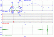
Another image, with transfer char. and its derivative (for connoisseurs 😉 )
Attachments
PMA, ultimately we should use a floating voltage source with a small series R. There may actually be an optimum R for a given current and transconductance.
PMA, another interesting variation would be a 10-100 ohm resistor across the sources but horizontal rather than vertical. This will control the gain, but it might add distortion also. You already did something similar, but you used 51 ohm resistors. I would use 10 ohms or less. This should be both interesting and practical.
I am concerned that the jfets do not seem to behave like real world devices. We may have to align the parameters to be more self consistent. Still, very good work, even I am impressed with this simulation. This is an ideal where simulation is most useful, in my opinion, because you can try 'what ifs' without too much trouble, going so far as to use idealized devices at least at first, for clarity.
I am concerned that the jfets do not seem to behave like real world devices. We may have to align the parameters to be more self consistent. Still, very good work, even I am impressed with this simulation. This is an ideal where simulation is most useful, in my opinion, because you can try 'what ifs' without too much trouble, going so far as to use idealized devices at least at first, for clarity.
IMHO we do not meet effort here (I mean finding a resistor).
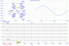
For the image attached:
1) 2SK389V/2SJ109V, Id=10mA, dId=1mA, dVss = +1.477V
V5 = +1.1V, R7 = 18.8R, D3 (3rd harm dist) = 0.007uA
V5 = +1.3V, R7 = 8.8R, D3 = 0.005uA
2) 2SK389BL/2SJ109BL, Id=10mA, dId=1mA, dVss = -60mV
V5 = -0.2V, R7=7R, D3 = 0.008uA
V5 = -0.1V, R7=2R, D3 = 0.008uA
V5 = -0.3V, R7=12R, D3 = 0.009uA
Attachments
john curl said:PMA, another interesting variation would be a 10-100 ohm resistor across the sources but horizontal rather than vertical. This will control the gain, but it might add distortion also.
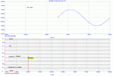
It reduces distortion, and for BL grade we have about 10mA Id without floating DC source. This is for 100R, I can try 10R and return in case of significant difference.
Attachments
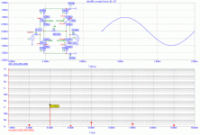
For 10R, we have 0.0007% compared to 0.0002% with 100R. So, this kind of local FB reduces distortion.
With 0R (no FB), we have 0.0009% for this circuit with BL grade devices.
With 0R (no FB), we have 0.0009% for this circuit with BL grade devices.
but, at that low level, are they real? or artifacts arising from the algorithm?PMA said:BUT in case we increase tha gain regulating (FB) resistor to 100R, the higher harmonics start to appear, though the 2nd is decreased.
Good question, but they absent for 10R. And they become higher again for 1k, compared to 100R. It looks similar like in case of degeneration of simple JFET, see
http://web.telecom.cz/macura/diyaudio/jfetdist.htm
the page is continuously updated.
http://web.telecom.cz/macura/diyaudio/jfetdist.htm
the page is continuously updated.
Good work, PMA, and welcome to Charles Hansen's and my world of audio design. You know, what if I do this, what happens? 

Good day Mr. Curl
You built in a phase switch in the Blowtorch , so i assume the benefits with the absolute phase must be higher than the losses due added solderjoints , wiring etc.
With search i found no real help why this should be so important , altough with some gear and records i can hear a difference .
Is there a link or something else helping me answer my question ?
Frank

Groove T, even Dr. Lipshitz believes in absolute polarity. Don't worry, just listen, BUT you must use a GOOD switch, not a cheap one.
We use this really big and bad Shallco silver on silver switch, for example. It is VERY long because it has 4 separate poles,and is hard to turn. That is 'quality'.
I wonder if the distortion spectrum changes if you increase the input voltage swing by, say, 20dB ??
Patrick
Patrick
- Status
- Not open for further replies.
- Home
- Amplifiers
- Solid State
- John Curl's Blowtorch preamplifier
