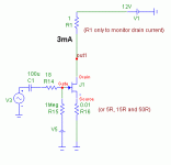
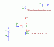
PMA said:Let's go on a bit. See effect of degeneration at single JFET, lambda = 10m, source resistor = 50R
Could you describe the circuit in more detail - Vds and the value
of any Drain resistance?
Nelson Pass said:
Could you describe the circuit in more detail - Vds and the value
of any Drain resistance?
Sure.
Attachments
Right on, PMA. It is OK now to go forward and your simulation shows what we would expect. The only minor question is why you did not set Lambda to zero? Just to give the equations a base line, and then add increased Lambda?
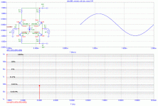
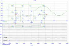
This is a very good point. Even for lamda=0, there is a 3rd and 5th order distortion with degeneration, only a little bit smaller, then for lamda = 10m. Without degeneration and Rd near to 0, there is only pure 2nd.
The answer is, I would guess, that bias, therefore Vgs is affected by degeneration resistor voltage drop, Vgs is one of the variables in equation showed yesterday.
Syn08, my assocate did come back with a slightly different set of equations. The problem is to interpret them into real world (even if idealized) devices.
So far I have:
single device: H2 = b2/b1 = 1/4 Via/(Vgg-Vt) (I was advised to make Vt = 1 for convenience).
diff, devices H3 = b3/b1 = 1/32 [Via/(Vgg-Vt)] squared.
You have most probably said just as much in your equations, thus far.
Unfortunately it is still difficult to compare the two distortions at this point as one is controlled by square law.
However, to just equate them, and find a reference point might be interesting, as it would show where on the operating point that the 2'd harmonic of a single fet would equal the 3rd harmonic of an ideal diff pair.
Then we might put in realistic lambda for the fets and note the difference.
After, we might try resistive degeneration, much like PMA has already started.
Finally, we might find what complementary differential fet input does and how the two fet pairs interact, and if there is an ideal operation point or condition for best overall distortion, especially maintaining lower order and minimizing higher order, such as 5th and especially 7th.
I do have the class notes that my associate sent me, if you want me to forward them. They are only a few pages, and some of what I got was from Don Pederson's book was well.
John,john curl said:Finally, we might find what complementary differential fet input does and how the two fet pairs interact, and if there is an ideal operation point or condition for best overall distortion, especially maintaining lower order and minimizing higher order, such as 5th and especially 7th.
probably you will hate me now, because I again only fill in unbacked information.... see it (this goes to the other contributors as well) as food for thought:
Assume we define a tolerance band within gm might change for a given maximum drive. If the band is virtually zero width, only D2S qualifies.
If we allow a small change my math intuition tells me that we then need a gm curvature with the smoothest rate of change to get the lowest amount of higher order harmonics, most probably at the cost of increased lower order amounts and increased (non-optimum) overall distortion in the small signal area (say, 1/10th or lower max drive).
That's the hypothesis: the more rapidly gm changes while the signal cycles through the whole range the more higher harmonics are produced. Assume a step change in gm, it will produce a step change in the output waveform also, obviously creating lots af nasty high order stuff. The rate of change has a "infinity" spot in it, but any sudden gm slope (step change in rate of change of gm) will likewise produce higher harmonics.
The smoothest rate of change is a constant rate of change, which then means the gm vs. drive curve should approximate a parabola.
- Klaus
EDIT: spelling & removing too much speculative things...

john curl said:Syn08, my assocate did come back with a slightly different set of equations. The problem is to interpret them into real world (even if idealized) devices.
So far I have:
single device: H2 = b2/b1 = 1/4 Via/(Vgg-Vt) (I was advised to make Vt = 1 for convenience).
diff, devices H3 = b3/b1 = 1/32 [Via/(Vgg-Vt)] squared.
You have most probably said just as much in your equations, thus far.
Unfortunately it is still difficult to compare the two distortions at this point as one is controlled by square law.
However, to just equate them, and find a reference point might be interesting, as it would show where on the operating point that the 2'd harmonic of a single fet would equal the 3rd harmonic of an ideal diff pair.
Then we might put in realistic lambda for the fets and note the difference.
After, we might try resistive degeneration, much like PMA has already started.
Finally, we might find what complementary differential fet input does and how the two fet pairs interact, and if there is an ideal operation point or condition for best overall distortion, especially maintaining lower order and minimizing higher order, such as 5th and especially 7th.
I do have the class notes that my associate sent me, if you want me to forward them. They are only a few pages, and some of what I got was from Don Pederson's book was well.
My coefficients were exactly half of your associate's, and that's most likely because of a confusion with the bias source value (Io vs. 2*Io).
But anyway, as you probably noticed, the ratio between the single ended H2 and the differential H3 is a constant (for the non-degenerated stages, devices with parabolic models). Therefore, I don't think there's here a sweet spot in this single ended vs. diff game. In this sense, the ratio of H2 to H3 is kinda "best case".
As Klaus also mentioned, for a particular JFET model, biasing and keeping the excursion as small as possible and only in the parabolic region (so avoid the places where lambda matters) are the only ways I can think of in decreasing the distortions, both for single ended and for diff stages. Whatever way you are crossing this region (Vgs or Vds) you only add more distortions to both single ended and diff stages outputs.
There is more to this. For example, what if we made a complementary folded cascode single sided design, rather than a differential complementary folded cascode design?
What happens when vacuum tubes are used differentially?
What about REAL FETS?
We know that real fets have some channel length modulation. Is the third generated by this process additive or subtractive to the third generated by differential operation?
You see, there are many questions that now can be addressed.
Actually, at this point, it might be that simulation would give us faster and easier answers. PMA may have to lead the discussion at this point, with his simulations.
This is a very interesting task. However, due to different time zone here and lot of work I am quite tired this evening. I will take a break and continue tomorrow, I am sure that simulation will give us some interesting answers again.
PMA said:For completely dc coupled, result is the same.
What was your drive voltage?
Well, I believe to come in a couple of hours with first webpage, summarizing our recent effort. It takes some time to get a result that makes sense and I hope you will tolerate that I prefer to create a web page rather than continue in single posts.

- Status
- Not open for further replies.
- Home
- Amplifiers
- Solid State
- John Curl's Blowtorch preamplifier