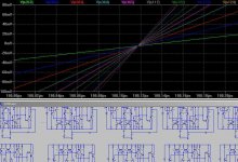
KSTR said:I for one can *not* exactly reproduce Pavel's "PIM"-graphs, but slightly different ones, still showing some zero crossing shift with increased amplitude.
Albeit with a different amp (F5-style, but with bjt diamondbuffer frontend, which doesn't matter much in this context). It is compensated for decreased open-loop gain above the audio band (pole/zero pair) to better handle cap loads (10nF used here). When I remove the compensation and cap load, I get the similar curve "distortion" as Pavel with his dispre vs. 5532, better correlated zero crossings and overall shifted in time.... until I zoom in further...
Test freq was 40kHz to get a clear picture 😉, and drive from 10% to 100% (of just below clipping level) into 5.6R.
EDIT: I recognize my graph doesn't match Pavel's
- Klaus
Ermm......... Is this being done with square waves (like by someone else in another thread 🙄 ) or with sinewaves?
If the former, then the experiment is a load of baloney.
There is no point trying to prove anything negative about a dominant pole compensated, high nfb amplifier in this regard by forcing it into slewrate limiting because when the amplifier slew rate limits the global negative feedback in inactive.
To prove the point attached below is a sim of an opamp of the topology most feared by the golden ear fraternity - a dominant pole compensated amplifier with an open loop bandwidth of a few tens of Hz. It slews 40V/us, has a unity loop gain frequency of about 1.3MHz and a closed gain of 10. The design is my fully complementary topology with current mirror loaded LTP's and improvised VAS baising. It has next to no THD.
The sim was run with a 40kHz SINEWAVE, input amplitudes stepped from 0.1V to 1V.
The global negative feedback blows the PIM distortion into oblivion.
Attachments
Outstanding!
don't stop now...
...the only book that I ever found on the subject of the innards of opamp/ICs was by Allan Grabeane (sp?), iirc. Excellent, imho.
Any other suggestions as to outstanding texts would be appreciated...
_-_-bear
don't stop now...
...the only book that I ever found on the subject of the innards of opamp/ICs was by Allan Grabeane (sp?), iirc. Excellent, imho.
Any other suggestions as to outstanding texts would be appreciated...
_-_-bear
Q.E.D.
May I ask you, Ovidiu, what if something unknown is still there? E.g., in loudspeaker design they are talking now about frequency dependent directivity factor (beaming), which was brought 15 years ago or even earlier and was heresy, and now is a dogma. What about PMA simulations, which looks like late Otala PIM? Are we aware about 1st Watt range? If the answer is positive let us analyze the signal in several dimensions.
Ovidiu, I’d designed taking into account frequency response, input and output impedance, crosstalk, THD+N, individual harmonic levels, CMRR, PSRR, EMI susceptibility, radiated EMI, etc, etc everyday for each and every building block in the system.
Why couldn’t we discuss alternative to overall FB schemes? Life is boring without challenges.
Glen,
Sine wave, of course.
And as I said it's a matter of zoom factor until you see that shifts, therefore it's basically only ok IMHO to use it for A/B-comparisons, which is just what PMA did.
As of now I'm completely unsure how to interpret this graphs anyway. In my case they might just be sim artifacts, although the MOSFET models used are supposed to be good ones ("hand-matched" by andy_c).
- Klaus
>Why couldn’t we discuss alternative to overall FB schemes?
Obviously no stinkin 'overall FB' or even FB around 2 stages
comes to mind. (or any FB other than degenerative)
Obviously no stinkin 'overall FB' or even FB around 2 stages
comes to mind. (or any FB other than degenerative)
bear said:...the only book that I ever found on the subject of the innards of opamp/ICs was by Allan Grabeane (sp?), iirc. Excellent, imho.
Any other suggestions as to outstanding texts would be appreciated...
Well, this isn't a text, but an app note that was taken from a 1974 article in the IEEE Journal of Solid State Circuits. It's The Monolithic Operational Amplifier: A Tutorial Study by Solomon. It's dated but very nicely done.
And this reminds me of a question I had intended to ask Scott. Does the output stage dissipation of modern IC op-amps still cause variations of open-loop gain due to thermal effects as described by Solomon in this paper? If not, what has changed?
KSTR said:Glen,
Sine wave, of course.
And as I said it's a matter of zoom factor until you see that shifts, therefore it's basically only ok IMHO to use it for A/B-comparisons, which is just what PMA did.
As of now I'm completely unsure how to interpret this graphs anyway. In my case they might just be sim artifacts, although the MOSFET models used are supposed to be good ones ("hand-matched" by andy_c).
- Klaus
Well OK then.
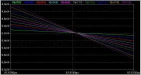
Just for further comparison purposes, here is my opamps 40kHz zero crossings zoomed in to a horizontal scale of 600 pico seconds (0.0000000006 seconds 😀 )!
I'm not convinced of the "inherent" evils of high global nfb and dominant pole compensation from a "PIM" perspective so far

Attachments
@bear:
http://www.designinganalogchips.com
has a nice downloadable book by Hans "Mr.555" Camenzind.
It's a "little bit of everything", but there are some insights what makes IC design so different and difficult.
- Klaus
http://www.designinganalogchips.com
has a nice downloadable book by Hans "Mr.555" Camenzind.
It's a "little bit of everything", but there are some insights what makes IC design so different and difficult.
- Klaus
john curl said:Well, Duh! I read that in 1974. Where have YOU been?
Wow, so you can read. Very good.
john curl said:Well, Duh! I read that in 1974. Where have YOU been?
Well, my post was in response to Bear. No need to be rude and condescending.
hitsware said:>Why couldn’t we discuss alternative to overall FB schemes?
Obviously no stinkin 'overall FB' or even FB around 2 stages
comes to mind. (or any FB other than degenerative)
What's wrong with "stinkin overall feedback" ?? Please explain ??
Some day the Stygian Witches will cut this thread of life and all will be clear.
I know this does not help, or is not helpful, I'm sorry in this case I do not care.
I know this does not help, or is not helpful, I'm sorry in this case I do not care.
I like Pavel's trick of showing PIM using a transient simulation of different amplitude sine waves. It's quite clever and innovative.
I do have a couple of concerns though. Let's say the circuit being simulated has second-order distortion that does not cause PIM. Then the increasing signal amplitude could cause a DC output shift, which could be misinterpreted as phase modulation because of the shifted zero crossing. Maybe it's better to look at the phase of the fundamental of the FFT of the output?
The other concern I have is op-amp models. If the model is device-level, then that's fine. But most op-amp models are of the macro-model type, which aren't intended to model distortion at all. So they should be used with care in that application. I'm thinking specifically of the 5532 model that was used above.
scott wurcer said:I know this does not help, or is not helpful, I'm sorry in this case I do not care.
Scott, any comment on my question in the post above?
I do have a couple of concerns though.
Agreed, where is transition from negative to positive for the same circuit?
- Status
- Not open for further replies.
- Home
- Amplifiers
- Solid State
- John Curl's Blowtorch preamplifier