I have been a professional designer for more than 40 years, and your input precedes my more than 40 years of experience. It is the equivalent of 'trash talking' or teenage bluster. Why? Where are the moderators? Must the lowest common technician level circuit be put up with serious designs? Why this thread? Is there no other space?
>The 1 Meg resistor used in the gate-drain
>circuit of the first FET is providing negative feedback !!
It appears that way, but in practice doesn't seem to happen
I.E. a resistor in series with the input does not cut down
the gain at all ...... except for the voltage divider effect with the
100k ......
However so then bias the input from the + rail
To forgo any ambiguity .......
>I could provide many examples
>of feedback amplifiers which
>perform even better so what
>are all of these issues with
>feedback amplifiers ??
>Please explain ??
Do you have one example of a feedback amplifier that
sounds better than a non-feedback amplifier .....
Not at any given 'rating' for sure ...
>of feedback amplifiers which
>perform even better so what
>are all of these issues with
>feedback amplifiers ??
>Please explain ??
Do you have one example of a feedback amplifier that
sounds better than a non-feedback amplifier .....
Not at any given 'rating' for sure ...
hitsware said:Do you have one example of a feedback amplifier that
sounds better than a non-feedback amplifier .....
Not at any given 'rating' for sure ...
What a powerfull argument.
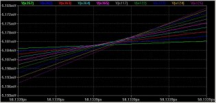
It is a sine of constant frequency with amplitude as a parameter. Magnified zero crossing. Example was for 100kHz, but you find it for 10kHz as well. 5532 is a spice model. You can get any VFB opamp, or discrete VFB dominant pole compensated. You do not get it from passive RC of same BW. And you do not get it from a structure with such Bode plots (v👎-v(i) is differential input voltage):
The problem is only a question of a measure, just magnify to find it. And it is logical - read Walt Jung Paper.
The problem is only a question of a measure, just magnify to find it. And it is logical - read Walt Jung Paper.
Attachments
hitsware said:>The 1 Meg resistor used in the gate-drain
>circuit of the first FET is providing negative feedback !!
It appears that way, but in practice doesn't seem to happen
I.E. a resistor in series with the input does not cut down
the gain at all ...... except for the voltage divider effect with the
100k ......
However so then bias the input from the + rail
To forgo any ambiguity .......
Sorry I stand corrected !! The feedback depends on the source impedance but the circuit is definitely mediocre and certainly doesn't explain why negative feedback is not good !!
PMA said:The problem is only a question of a measure, just magnify to find it. And it is logical - read Walt Jung Paper.
With my basic 40V/us SR, 1.3MHz BW opamp I need to zoom the horizontal scale in to a span of 10ps to see the jitter (which is <2pS overall for 1V to 10V peak output) with a 20kHz sinewave.
If I extend the unity loop gain frequency (which can be easilly extended several MHz without stability issues) by reducing the value of the miller compensation capacitors the jitter reduces proportionally.
Is this really a problem?
Attachments
PIM
Hi Glen,
Really not bad. The MCP amp does 11ps (1-30V-pk)
BTW, I wonder how reliable are these simulated figures.
Cheers,
Edmond.
G.Kleinschmidt said:With my basic 40V/us SR, 1.3MHz BW opamp I need to zoom the horizontal scale in to a span of 10ps to see the jitter (which is <2pS overall for 1V to 10V peak output) with a 20kHz sinewave.
.........
Hi Glen,
Really not bad. The MCP amp does 11ps (1-30V-pk)
BTW, I wonder how reliable are these simulated figures.
Cheers,
Edmond.
Re: PIM
That's a good question. Anyway, try a sim at 100Hz instead of 20kHz where the loop gain is much higher. Then we are talking phase shifts in femto seconds. I see no valid argument for wide openloop bandwidth here.
I guess it all boils down to the well proven fact that if your amp has neglible THD at any audio frequency, then it will almost certainly have neglible amounts of any other measurable non-linearity (PIM, IMD, TIM, BOB, JOE, ZOE etc) as well.
Cheers,
Glen
Edmond Stuart said:BTW, I wonder how reliable are these simulated figures.
That's a good question. Anyway, try a sim at 100Hz instead of 20kHz where the loop gain is much higher. Then we are talking phase shifts in femto seconds. I see no valid argument for wide openloop bandwidth here.
I guess it all boils down to the well proven fact that if your amp has neglible THD at any audio frequency, then it will almost certainly have neglible amounts of any other measurable non-linearity (PIM, IMD, TIM, BOB, JOE, ZOE etc) as well.
Cheers,
Glen
PIM
Sure, all these distortion thingies are inter-related.
As for accurately simulating/measuring PIM, maybe one should look at the phase jitter obtained by FFT's instead of looking at the zero-crossings.
Cheers,
Edmond.
Sure, all these distortion thingies are inter-related.
As for accurately simulating/measuring PIM, maybe one should look at the phase jitter obtained by FFT's instead of looking at the zero-crossings.
Cheers,
Edmond.
I don't know how to measure it with real devices at this time, PMA, but it is EXACTLY what we would have predicted from the mathematics of Matti Otala almost 30 years ago, and the following analysis by Barrie Gilbert. Just like jitter.
Thinking a little and playing with ideal sources and distortion mechanisms in LTspice, I now found that I get these ZC shifts whenever a distortion mechanism is followed with anything that doesn't have constant group delay for the frequencies covered by the produced harmonics.
Something like a plain x+0.001*x^3, around the corner freq. of a simple RC lowpass. Or if the lowpass itself is somewhat nonlinear. It's not a feedback vs. no feedback question.
Sorry John if this is boring news for you, but others may find it interesting...
- Klaus
Something like a plain x+0.001*x^3, around the corner freq. of a simple RC lowpass. Or if the lowpass itself is somewhat nonlinear. It's not a feedback vs. no feedback question.
Sorry John if this is boring news for you, but others may find it interesting...
- Klaus
Not boring to me, but I have known about it for decades. This is one of the major factors in our more radical design departures from the simple op amp model that we know so well.
I now found that I get these ZC shifts whenever a distortion mechanism is followed with anything that doesn't have constant group delay for the frequencies coververd by the produced harmonics.

Thanks for the citations...
I was thinking more about advanced level texts/books/articles... more along the lines of what this thread has bandied about so nicely.
The Grabaene book I have is of that sort, in depth analysis of advanced analog IC design, but was hard to find and I have yet to find anything else quite like it - has anyone else run across it?
Those of us who have not had the benefit of a first class EE education have to run hither and yon picking up tidbits along the way in a hodgepodge trying to put together a reasonable picture - which is problematic to be sure. Keep in mind that there are very few books that seem to manage to even mention something as basic as a Baker clamp... much less who the heck was "Baker."
Sorry to impose with such obvious ignorance...
_-_-bear
books by Alan B. Grebene
1. Bipolar and Mos Analog Integrated Circuit Design, John Wiley & Sons Inc (November 2002)
2.Analog Integrated Circuit Design, Van Nostrand Reinhold Co (January 1972)
3. Integrated Circuit Processes, McGraw-Hill (January 1978)
4. Integrated Circuit Devices and Components McGraw-Hill (January 1978)
1. Bipolar and Mos Analog Integrated Circuit Design, John Wiley & Sons Inc (November 2002)
2.Analog Integrated Circuit Design, Van Nostrand Reinhold Co (January 1972)
3. Integrated Circuit Processes, McGraw-Hill (January 1978)
4. Integrated Circuit Devices and Components McGraw-Hill (January 1978)
I tried this morning to do some PIM measurements on the high speed opamp based line preamp.
I tried to measure the output zero crossings (with respect to a input signal trigger) at 100KHz, both for sine and square inputs. The sine input was a -110dB pure from my analyzer, while the square wave was provided by a 50MHz synthesized generator with rise and fall times of around 1nS. The synthesizer also provides a highly accurate trigger output that I used to externally trigger the scopes.
My analog 2465A (350MHz) and digital TDS3052 (500MHz) have 5nS/div and 1nS/div time base ranges, allowing to visually estimate 500pS and 100pS respectively. I have aquired the results (as a time delay from the trigger point) through a HPIB interface and averaged over multiple (100) measurements.
For a range of 1Vv-10Vv output levels (that is, 100mVv to 1Vv inputs) I was unable to identify any statistically significant zero crossing dependency on the signal level.
I have also tried to drive the preamp with a square wave of about 500KHz (which is around the closed loop bandwidth), still nothing.
I have tried to load the preamp with capacitive loads up to 10nF, still no measurable dependency on signal level or frequency, only a constant delay.
I repeated the above for the 600V/us preamp (opamp + 2SC3601/2SA1407 trannies, built on microstrip) with -110dB distortions and 10nV/rtHz noise (I'll post the schematic later today). Still nothing, zip, nada.
I currently do not have the tools and means to measure anything in the pS range where probably the effect is, but if somebody could give me a good reason why a pS range phase jitter should matter in audio, then I'm all ears. 🤐 this is audio, not GHz range radar technology.
- Status
- Not open for further replies.
- Home
- Amplifiers
- Solid State
- John Curl's Blowtorch preamplifier