Sigurd Ruschkow said:it is not DC voltage that causes the click sound, so it must be the ELMA rotary switches that is the cause. I can stand the clicks but they are annoying as it feels that the design is not finished. Personally, the clicks have to go.
You may still be able to get rid of the clicks by spraying the pads and viper with no residue contact cleaner. Elmas have tendency to click initially but after clean up they are usually quiet.
There are also two versions of those switches, from Percy's catalog:
"The 04-2130 features their standard premium grade construction
but does exhibit some slight contact bounce which may cause varying degrees of transient noise when switching between positions, usually insignificant
but this could be a problem in some applications so beware! The BV switches were specifically designed for attenuator applications and have no contact
bounce: they utilize PC boards for each deck with special trace material for the contacts."
Regarding the previous comments about fixed series/variable shunt attenuators; one has to look into it from a practical point of view as well. I don't know how much some of you like to play with volume control, but I ususally never go beyond 10dB variation range. For a 10k series resistor value, when changing volume from -10dB to -20dB (about all I use personally), the shunt element changes from 4k to 1k which gives approx 20% total input resistance change. Could that be regarded as negligable and small price to pay comparing to elaborate ladder circuits that beside using double the components number also create additonal contact points?
Of course, it is a different matter for a full featured commercial product, however in most diy applications it shouldn't be much of a problem or limitation.
Regarding TC TX2352 resistors, I like them as well, but in some parts of the circuit Caddocks just perform better; especially in an input shunt position and I always choose them over Vishays here.
Attachments
Hello Daniel,
that is one heck of a nice stepped attenuator you have made!
Mk132s in the shunt positions and then a TX2352 in the series position might be darn good combo. I might try that some day - then it will be with Shallcos.
As usual, personal preferences affects what one finds is the better combination 🙂
Thanks for the tip about the cleaner. That must be tested!
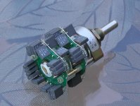
Yes, I know about the special versions for attenuators. I am only using those. Attached is my ladder attenuator which uses the ELMA rotary switch with four PCBs attached to it.
Depending on how large and heavy the knob is, the click sounds differ. I have tested knobs made outof solid brass from 10mm up to 70mm, and with the 70mm one I can do extremely slow turns of the rotary switch and notice how the make before brake action is working. With a 10mm know the rotary switch is more like tic-tic-tic.
Still, as Charles Hansen kindly pointed out, the make-before-brake action actually connects two resistors in parallel each step with a fixed series/variable shunt stepped attenuator. This wil change the gain in the middle of two volume settings and depending on where in the music wave one changes the volume setting, there will be a click sound.
Sigurd
that is one heck of a nice stepped attenuator you have made!
Mk132s in the shunt positions and then a TX2352 in the series position might be darn good combo. I might try that some day - then it will be with Shallcos.
As usual, personal preferences affects what one finds is the better combination 🙂
Thanks for the tip about the cleaner. That must be tested!
Yes, I know about the special versions for attenuators. I am only using those. Attached is my ladder attenuator which uses the ELMA rotary switch with four PCBs attached to it.
Depending on how large and heavy the knob is, the click sounds differ. I have tested knobs made outof solid brass from 10mm up to 70mm, and with the 70mm one I can do extremely slow turns of the rotary switch and notice how the make before brake action is working. With a 10mm know the rotary switch is more like tic-tic-tic.
Still, as Charles Hansen kindly pointed out, the make-before-brake action actually connects two resistors in parallel each step with a fixed series/variable shunt stepped attenuator. This wil change the gain in the middle of two volume settings and depending on where in the music wave one changes the volume setting, there will be a click sound.
Sigurd
Attachments
I do not know why you still speculate about the CTC circuit schematic (local feedback at input stage, one resistor), for the reason that it was shown in this thread at least 3 times, except for DC servo circuit.
Sigurd Ruschkow said:Depending on how large and heavy the knob is, the click sounds differ. I have tested knobs made outof solid brass from 10mm up to 70mm, and with the 70mm one I can do extremely slow turns of the rotary switch and notice how the make before brake action is working. With a 10mm know the rotary switch is more like tic-tic-tic.
Still, as Charles Hansen kindly pointed out, the make-before-brake action actually connects two resistors in parallel each step with a fixed series/variable shunt stepped attenuator. This wil change the gain in the middle of two volume settings and depending on where in the music wave one changes the volume setting, there will be a click sound.
It may be that the heavy knob affects mechanical alignement of the contact elements in the Elma switch, after all they are pretty fragile. In such cases I would recommend shaft extenders which should reduce any such behaviour.
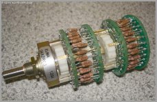
The attenutaor in my picture above had some switching noise initially but after clean up it's completely quiet. That was also confirmed by a friend of mine who built similar attenuator.
I use Elma in my TVC based preamp and after 3 years it's still trouble free: http://www.diyaudio.com/forums/attachment.php?s=&postid=879147&stamp=1143477205
PMA said:I do not know why you still speculate about the CTC circuit schematic...
At least in my case, the answer is quite simple...I'm interested in any reasonable variant of this general topology. I'm pretty well locked into one version at the moment and it's performing very nicely indeed in my current amp. I've got at least two other versions that I can go to for my next circuit, but who knows...maybe there's an interesting turnoff I missed whilst following the main highway.
Grey
Agreed. I can whomp solid state circuits employing fifty transistors with less than ten tubes--and that's even having to make allowances for the confusticated output transformer (in the case of power amps). Unfortunately, I just can't justify messing with tubes any more. My goal is to claw my way back up to that sonic level using solid state.
Yes, I know more learned men than I have tackled the problem and come up short, but that doesn't mean I can't give it a shot.
Grey
Yes, I know more learned men than I have tackled the problem and come up short, but that doesn't mean I can't give it a shot.
Grey
John,
It could be that I am wrong about where I read your remark about local feedback in the second stage and if it was not in this thread it must have been in the compendium that was released on another forum.
Now many discussions about feedback have already been held in other threads. So I will not start another one here. I only want to point out, that as I have understood, you mentioned that there is LOCAL feedback used in the SECOND stage of the BT. To me the BT has TWO stages and the SECOND stage to me is the stage using the output Mosfets. The FIRTS stage I consider to be the input stage using JFets.
If you can point out what YOU see as the first and second stage of the BT, I think it will be clear for all of us what you really mean.
Thanks in advance
John, here's what you wrote in some thread somewhere about the BT concerning feedback:
"The CTC preamp uses an open loop input stage, a low feedback second stage, and no global feedback line stage, all direct coupled, ultra low noise, and balanced output operation."
Please correct me if I and maybe others have not understood what you meant. RE-reading the above statement I wonder if there actually are THREE stages used in the BT or not?
I wrote it wrong for some reason. Now I know, I was talking about the phono stage, NOT the line stage, specifically. The line stage is really just one stage, without global feedback.
OK John, your former remark was made with the phono stage in mind. But now it gets a bit confusing for me when you state:
"The line stage is really just one stage, without global feedback"
What I considered to be TWO stages in the line stage now turns out to be ONE stage? Can you explain your understanding of what is considered a stage and what not? From what I understand the JFets part is the FIRST stage and the output MOSFETS the SECOND stage. So can you clear this up?
Without GLOBAL feedback implies to me that there is LOCAL feedback, either in what I consider to be the FIRST or SECOND stage......
Thanks in advance.
There are several local feedbacks. Source resistors (R10, 11, 13, 14), interstage resistor R12. Output stage is current output, no feedback.
There is only a problem of language.
A STAGE in this example is an independent gain block.
There are 3 independent gain blocks in the CTC preamp that I own and use.
The first stage (gain block) is open loop.
The second stage (gain block) has negative feedback.
The third stage (gain block) which is located after the volume control, has no global feedback.
First of all thank you bob for your cery kind words.
To clarify things do you mean John:
“The first stage (gain block) is open loop.”
MC preamp + first time constant (open loop except mod for MM ?).
“The second stage (gain block) has negative feedback.”
MC preamp + second time constant around the feedback loop.
“The third stage (gain block) which is located after the volume control, has no global feedback.”
This is line stage, that I guess, all of us call the blowtorch.
The question here is: has this line stage some local feedback around the “output mosfets”
No Richard, that is your design. My design does NOT have feedback around the second stage. However, it is an interesting way to make the design, and I commend you for it.
- Status
- Not open for further replies.
- Home
- Amplifiers
- Solid State
- John Curl's Blowtorch preamplifier