Well......it’s like this. In a flea bay type situation i’d be lucky to get $1200 for it.
It’s more principal at this point......I see a good product that was taken from behind in manufacturing.
If I lose the patient I will not cry, I have a better sounding unit in use so I will not be without sound. And to tell you the truth I’m comfortable that I can make these mods without screwing it up.......I might come off as a moron in my quest for information but I’m really not.
I appreciate everyone’s concern though 🙂
Bob, I am sure you will get the hang of electronics soldering pretty quick if you practice on some junked boards first.
This kind of job is elementary and essentially zero risk despite Marks concerns.
Do you mind also to remove one of the connector boards and take a pic of both sides please?.
Dan.
This kind of job is elementary and essentially zero risk despite Marks concerns.
Do you mind also to remove one of the connector boards and take a pic of both sides please?.
Dan.
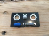
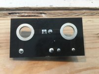
Ok thanks, exactly as I expected.Here ya go
Did you order/get a soldering iron yet ?.
Dan.
In clean domestic environment I have always found these connectors to be completely reliable, why "best bypassed or avoided" ?.CN1 100 best bypassed or avoided.
Dan.
It already had some oxidation forming on the pins.
I thought gold plating in contact with tin plating was not optimum either? (As in pcb to post/nut)
And I also thought that was the whole point.....to eliminate the connector?
I thought gold plating in contact with tin plating was not optimum either? (As in pcb to post/nut)
And I also thought that was the whole point.....to eliminate the connector?
Last edited:
Yes, and the pcb, best to wire direct to the banana posts like I have shown.And I also thought that was the whole point.....to eliminate the connector?
Dan.
In clean domestic environment I have always found these connectors to be completely reliable, why "best bypassed or avoided" ?.
Dan.
They carry full speaker current. You suggest direct soldering to a binding post as well, so why are you asking??
It already had some oxidation forming on the pins.
It can be seen from your photo. Oxidation + arc makes nothing appreciable.
Ok, same as you I am not in favour for this application, other applications I have no hesitation.They carry full speaker current. You suggest direct soldering to a binding post as well, so why are you asking??
Bob,
You might think about some questions before starting:
What is the amp worth if you sell it now in working condition?
Are you willing to risk complete loss of the unit if things don't turn out well?
How much money are you willing to spend experimenting with it?
X2; and if you're going to solder things directly, find which connections might actually matter and do only that so you lose the least serviceability, e.g. output to binding posts.
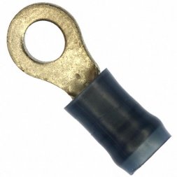
Use wire terminal , nut and spring washer for conection to binding posts, instead of soldering..
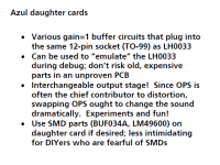
LH0033 hybrid as output stage of headphone amp
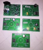
Although I had several LH0033s to play with, I didn't want to risk them in an unproven and not-bug-free amplifier board. So I decided to build an "emulator" daughter card, which plugged into the LH0033 socket and performed the same function, using low cost, easy to buy, active production components. If I destroyed a few of the emulator cards, so what. They're easily replaced.
Then the penny dropped. I realized that these LH0033 emulators were, in fact, interchangeable Output Stage Daughter Cards. I could swap new output stage designs in and out, as often as I liked. Perhaps to optimize measured performance, perhaps to optimize listening pleasure, perhaps to minimize parts cost, or perhaps to use up my stash of 1971 Linear Hybrid devices. Eureka.
Besides the LH0033 itself, here are some of the daughter cards I built to drop into the output stage socket. A couple of them use the "Objective 2 HPA" idea of parallel opamps with 1R5 balancing resistors; in my case, four parallel opamps, i.e. two duals. Then there's a BUF634A, an LME49600, and a discrete push pull buffer using 200 MHz VAS transistors in the TO126 package. And, perhaps, more to come.
_
Attachments
Mark you probably answered this earlier (apologies) but is your LH0033 circuit a composite or sequential stages? I'm assuming the latter or you had a lot of loop gain compensation practice! Cool stuff.
Daniel, it's a composite. However the LH0033 is only a unity gain buffer so it doesn't increase the loop gain. It does add a few degrees of phase shift at the unity gain frequency of the entire loop.
Here are the exhibit plaques that I placed next to the amplifier on display at Burning Amp. I think they probably tell you exactly what you want to know.
MJ
{I did exhibit another composite amplifier called "Rojo", with a total of ~180 dB of loop gain. An IC opamp in series with a high power discrete opamp. Yes it was fun to figure out how to compensate that unholy swamp. No it didn't use LH0033s.}
_
Attachments

Last edited:
As they say, curiosity killed thePlease keep it as it is. The soldering points shown by Max in the first picture may be connected to the terminals with thin traces, can't see because they are on the flip side. To solder there if that is the case would make matters worse.
The other picture underscores Max's lack of insight. Of course, the Zobel does not have two resistors.
There is guaranteed nothing to be gained sonically from bypassing the PCB connector.
You've been informed about the "fool's errand" relating to this attempt. It's now up to you to digest the info.Hey don’t worry about my feelings, I appreciate the point/counterpoint........helps one make more informed decisions.
The end result of Marks composite amp seemed pretty good. Old technology becomes art and useful at that.
Daniel, it's a composite. However the LH0033 is only a unity gain buffer so it doesn't increase the loop gain. It does add a few degrees of phase shift at the unity gain frequency of the entire loop.
Here are the exhibit plaques that I placed next to the amplifier on display at Burning Amp. I think they probably tell you exactly what you want to know.
MJ
{I did exhibit another composite amplifier called "Rojo", with a total of ~180 dB of loop gain. An IC opamp in series with a high power discrete opamp. Yes it was fun to figure out how to compensate that unholy swamp. No it didn't use LH0033s.}
_
Ah very cool! Sounds like it was a fun and fulfilling project. Reminds me that I have a bin of rescued TDA7293's that I was going to build an unholy front end for and tap in for their outputs. Logical? No, but fun in its arbitrariness.
Pavel -- one gets the impression that using the LH0033 was more for the challenge and satisfaction of marrying "ancient" parts in a modern way than for the absolute best performance money could buy.
Last edited:
- Status
- Not open for further replies.
- Home
- Member Areas
- The Lounge
- John Curl's Blowtorch preamplifier part III