I looked at the schematic and saw the one 4 amp fuse so if you added a second 2.5 amp
It is described by words in red (to emphasize) just near START1 block, you have probably overlooked it when checking the schematics. However, it is unimportant, my curiosity is about your 12% loss of output power because of the fuse resistance. You know Ed, statements like this always immediately rise eyebrows of some of us. Please appreciate how tolerant and patient I am (today) 😉.
Yah anything would be helpful......this piece really has potential to be better.
A lot of wires of all kinds and low cost connectors, right? You know, always do a reality check and do not believe much what is being written or said 😉
It is described by words in red (to emphasize) just near START1 block, you have probably overlooked it when checking the schematics. However, it is unimportant, my curiosity is about your 12% loss of output power because of the fuse resistance. You know Ed, statements like this always immediately rise eyebrows of some of us. Please appreciate how tolerant and patient I am (today) 😉.
Pavel,
In an amplifier running at 120 volts with a 1 amp fuse, the fuse losses will be 9.25 times greater than your setup if those are 3AG types even more if 5 x 20mm. I suspect you were surprised to find the losses in your test setup were as high as they were.
Have fun is the real issue.
I should add that the current rating of a fuse is based mostly on material and cross sectional area. The resistance is influenced by length. That is why 5 x 20 mm fuses have lower resistance than 3AG
Last edited:
Ed, a 1 amp fuse that survives a 2 x 120W amp running at 120V is a ticking time bomb. Get rid of it.... In an amplifier running at 120 volts with a 1 amp fuse, the fuse losses will be 9.25 times greater than your setup ...
A lot of wires of all kinds and low cost connectors, right? You know, always do a reality check and do not believe much what is being written or said 😉
Depends on who said it I would imagine. 😛
i’m sure your level of greatness is high but I respectfully question that none (or very few) of your measurements actually involve the reproduction of music.
@Bob: You can either look at informed modifications or 'glom for victory' and persuade yourself that things are going the right way. The latter route empties the wallet more...
Using either the Nailer from Dick Smith Electronics or the 1/4-20 No-Blo will do the trick.
the 1/4-20 No-Blo actually helps locate where the smoke is coming from.
Cheers
Alan
the 1/4-20 No-Blo actually helps locate where the smoke is coming from.
Cheers
Alan
Hey Bill,
That’s why i’m here....informed modifications.
I can’t help that some of my findings align with the minority sometimes, I seek no glory just good sound.
I’m slowly concluding that DSP based multi amp is the way to go......but I must work with what I have. When I researched it last yr before buying the Halo integrated was very well regarded by all but two different individuals who I thought were just ‘those people who could never be satisfied’ now I wonder. The saving grace is I got it after the new version came out and it was at a price I really couldn’t refuse.
It’s got a HT bypass so if worse comes to worse I can use as just an amp in my future DSP project. 😛
Former can empty the wallet too depending on the component but the results are more worthy than latter.@Bob: You can either look at informed modifications or 'glom for victory' and persuade yourself that things are going the right way. The latter route empties the wallet more...

Don’t worry much about all that........I don’t have enough disposable income to get into too much trouble! 😉
Apply the rule of reason. How could a small glass tube dissipate 30 W of energy without becoming glowing hot and starting to emit visible light?* So 12 % of a 2 x 115 W amp, I don't think so.
* there used to be an entire industry founded on that principle 🙂
* there used to be an entire industry founded on that principle 🙂
Yes, it makes the list _almost_ readable. It would be even better if fellow listers would stop quoting posts by resident trolls.This ignore list is a wonderful feature.
Friday Fun: 300 volt rated BJT survives 600V flyback pulse when switching relay coil
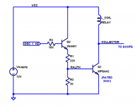
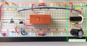
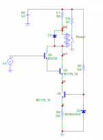
I built the little circuit shown in figures 1 and 2, on a solderless breadboard.
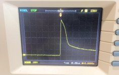
With no flyback diode and no flyback protection of any sort, I measured the waveform shown in figure 3, on the collector of the BJT. It's an MPSA42, whose datasheet shows an Absolute Maximum Rating of VCE <= 300 volts. But it seems to have survived just fine. I ran the apparatus for two or three minutes so it tolerated more than 100 flyback pulses at 600V each (!).
You'll notice that Figure 3 was taken on a very inexpensive digital scope. Yes it was my "most expendable" scope, which I used just in case the flyback pulse might prove injurious. With a 10 megohm 10X probe, the scope seems to have sustained no damage.
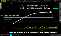
Then I pulled out a slightly nicer scope and did some two channel waveform captures. I measured the turn-off delay, with and without the traditional 1N4148 flyback diode across the relay coil. See Figures 4 and 5. Experimental result:
Anybody could replicate or extend the delay experiments; you probe only digital signals, which swing between DC supply (+12v for this relay) and ground. Benign and safe.
Circuit notes: R2 is only 30 ohms. This sucks out the base charge of Q1 very quickly (nanoseconds not microseconds) and speeds turn-off. Predriver Q2 is provided because the 1 Hz oscillator is made of CD4000 CMOS logic gates, which cannot source or sink much current at all. But they can run from a 12V supply, unlike TTL.
_
I built the little circuit shown in figures 1 and 2, on a solderless breadboard.
With no flyback diode and no flyback protection of any sort, I measured the waveform shown in figure 3, on the collector of the BJT. It's an MPSA42, whose datasheet shows an Absolute Maximum Rating of VCE <= 300 volts. But it seems to have survived just fine. I ran the apparatus for two or three minutes so it tolerated more than 100 flyback pulses at 600V each (!).
You'll notice that Figure 3 was taken on a very inexpensive digital scope. Yes it was my "most expendable" scope, which I used just in case the flyback pulse might prove injurious. With a 10 megohm 10X probe, the scope seems to have sustained no damage.
Then I pulled out a slightly nicer scope and did some two channel waveform captures. I measured the turn-off delay, with and without the traditional 1N4148 flyback diode across the relay coil. See Figures 4 and 5. Experimental result:
Relay turn-off was 5x slower with a flyback diode than without.
Anybody could replicate or extend the delay experiments; you probe only digital signals, which swing between DC supply (+12v for this relay) and ground. Benign and safe.
Circuit notes: R2 is only 30 ohms. This sucks out the base charge of Q1 very quickly (nanoseconds not microseconds) and speeds turn-off. Predriver Q2 is provided because the 1 Hz oscillator is made of CD4000 CMOS logic gates, which cannot source or sink much current at all. But they can run from a 12V supply, unlike TTL.
_
Attachments

Last edited:
A CFP would experience 600V pulses on both collectors. And if you needed a large base resistor on the driver, this might actually drive it into conduction during the voltage surge.
I built the little circuit shown in figures 1 and 2, on a solderless breadboard.
With no flyback diode and no flyback protection of any sort, I measured the waveform shown in figure 3, on the collector of the BJT. It's an MPSA42, whose datasheet shows an Absolute Maximum Rating of VCE <= 300 volts. But it seems to have survived just fine. I ran the apparatus for two or three minutes so it tolerated more than 100 flyback pulses at 600V each (!).
You'll notice that Figure 3 was taken on a very inexpensive digital scope. Yes it was my "most expendable" scope, which I used just in case the flyback pulse might prove injurious. With a 10 megohm 10X probe, the scope seems to have sustained no damage.
Then I pulled out a slightly nicer scope and did some two channel waveform captures. I measured the turn-off delay, with and without the traditional 1N4148 flyback diode across the relay coil. See Figures 4 and 5. Experimental result:
Relay turn-off was 5x slower with a flyback diode than without.
Anybody could replicate or extend the delay experiments; you probe only digital signals, which swing between DC supply (+12v for this relay) and ground. Benign and safe.
Circuit notes: R2 is only 30 ohms. This sucks out the base charge of Q1 very quickly (nanoseconds not microseconds) and speeds turn-off. Predriver Q2 is provided because the 1 Hz oscillator is made of CD4000 CMOS logic gates, which cannot source or sink much current at all. But they can run from a 12V supply, unlike TTL.
_
I was using the relay driver as attached. There was no advantage to omit D4, on contrary, D4 helps to restrict coil transients.
Attachments
Your scope photos didn't upload correctly
You mean this post?
John Curl's Blowtorch preamplifier part III
I do not know, I can see them normally, in case that I am logged in. They are png images.
- Status
- Not open for further replies.
- Home
- Member Areas
- The Lounge
- John Curl's Blowtorch preamplifier part III