but there are many other cases where it just signal doing it.
Ed, years ago you showed pictures from an OWON oscilloscope with an I/V characteristic that had 0 conductance at the origin and a break point of a few 10's of mV. Someone actually wondered if there were missing codes at the origin. There is no physics for this behavior, no bandgaps for any known elements support this. I admire your enthusiasm but tinkering around in a garage (or whatever) lab is not going to produce evidence that everything we know is wrong.
This effect has been called fritting and other names. It is well known that contacts in small signal relays have some small minimum voltage requirements.
Quoting the breakdown voltage of gasses is totally inapplicable.
A simple graph showing sulfur contaminated silver contacts re-establishing conduction at the levels mention can be found here:
Relay contacts and "fritting"
Quoting the breakdown voltage of gasses is totally inapplicable.
A simple graph showing sulfur contaminated silver contacts re-establishing conduction at the levels mention can be found here:
Relay contacts and "fritting"
Why is the behavior of dirty contacts considered something profound or useful? And as usual your reference describes micro-diode behavior.This effect has been called fritting and other names. It is well known that contacts in small signal relays have some small minimum voltage requirements.
Last edited:
Because it is a big issue at audio signal levels. Microdiodes would be directional. The initial high resistance that then drops and stays low after a signal voltage of 100 millivolts is not what would be expected from diode action.
You certainly can entertain yourself by doing an experiment or two. Just keep in mind once the contact resistance drops it stays low until a new film forms.
Pretty sure this is covered in Ragnar Holm's writings.
The folks who claim regularly cleaning or even using a low viscosity oil to keep out contaiments are not nuts. They just must be using physics unknown to you.
...The folks who claim regularly cleaning or even using a low viscosity oil to keep out contaiments are not nuts. They just must be using physics unknown to you.
Hoe dare you claim I am not nuts, legions of people before you cannot be wrong...I suggest you Cram-olin it yourself!
Howie
They just must be using physics unknown to you.
You prevent contaminated pathologicaly bad interconnects no problem with that, they do it a LIGO and every other serious research facility that I have known. On second thought there was no mention of tweaks of any kind when I was at LIGO 100's of cables just like the ones in any lab.
Just for clarity, yes micro-diodes.
The difference between the red and the blue curve is the polarity: red for the silveroxide electrode being negative, blue the other way around. We see a large difference between both polarities: that's the semiconductor effect mentioned earlier.
Last edited:
Come on Scott. Simon is correct. Whole books exist about contacts and films on the contacts and its effect.
LIGO uses gold contacts. No oxide build up. You should know that. Fake argument.
When oxidation or contaminating films, atmospheric pollution, the contact break-thru voltage eventually needs to be higher. That level depends on the oxide, contamination, film thickness etal. Gold and air-tight contacts are used for long term reliability.
THx-RNMarsh
Last edited:
Come on Scott. Simon is correct. Whole books exist about contacts and films on the contacts and its effect.
Totally ordinary stuff, nothing interesting or profound.
Totally ordinary stuff, nothing interesting or profound.
Agreed, the best heavy gold MIL connector contacts take advantage of gold's malleability and renew a gas-tight contact at each mating. Most consumer connectors are barely gold-flashed and wipe through the plating at the first mating. It is mostly base metal contact thereafter with the attendant intermittent oxidization problems...
Howie
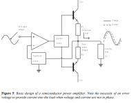
At the risk of attracting hate mail I would like to point out some wrong ideas (as if there are not enough). In Why do amplifiers sound different? there is this figure. The caption is incorrect, any feedback amplifier has an input error signal the phase of output current to voltage is irrelevant.
In fact for a basic "blameless" dominant pole compensated amplifier the error signal is in quadrature with the output signal. My favorite example is using a triangular wave (constant rate of change) as stimulus. The input error signal is the derivative of the output or in this case a square wave. The point often missed is that the feedback responds instantaneously (within the closed-loop BW limitations). Anyone can set this up in even the most basic lab, an op-amp connected as an inverter and look at the input error signal, nothing could be easier. So the delay and feedback goes round and round arguments are just simply nonsense.
In fact for a basic "blameless" dominant pole compensated amplifier the error signal is in quadrature with the output signal. My favorite example is using a triangular wave (constant rate of change) as stimulus. The input error signal is the derivative of the output or in this case a square wave. The point often missed is that the feedback responds instantaneously (within the closed-loop BW limitations). Anyone can set this up in even the most basic lab, an op-amp connected as an inverter and look at the input error signal, nothing could be easier. So the delay and feedback goes round and round arguments are just simply nonsense.
Attachments
Clean connections are very important with quality audio playback. Cramolin is one of the best contact cleaners on the planet. Relatively heavy Gold on Gold is the best way to keep 'micro-diodes' or whatever you want to call them, from developing.
At the risk of attracting hate mail I would like to point out some wrong ideas (as if there are not enough). In Why do amplifiers sound different? there is this figure. The caption is incorrect, any feedback amplifier has an input error signal the phase of output current to voltage is irrelevant.
In fact for a basic "blameless" dominant pole compensated amplifier the error signal is in quadrature with the output signal. My favorite example is using a triangular wave (constant rate of change) as stimulus. The input error signal is the derivative of the output or in this case a square wave. The point often missed is that the feedback responds instantaneously (within the closed-loop BW limitations). Anyone can set this up in even the most basic lab, an op-amp connected as an inverter and look at the input error signal, nothing could be easier. So the delay and feedback goes round and round arguments are just simply nonsense.
So what is new about this?
THx-RNMarsh
So what is new about this?
Nothing, not even the fact that many High End Audio priests don’t (or don’t want to) know it.
So what is new about this?
It's the crux of the Joe stuff which you jump on enthusiastically.
Oh I dont know about that. Just the part that over-laps with mine.
I am not defending him nor anyone -- only what I do, measure or hear.
THx-RNMarsh
I am not defending him nor anyone -- only what I do, measure or hear.
THx-RNMarsh
measure or hear.
These are not interchangeable. Correct: measure and hear (or not, thereof).
When we went from tube PAmps to SS, we noticed, by listening, that the bass was deeper, tighter, more accurate. Same effect occured when we used very thin speaker wires compared to thick (large AWG). Larger affected the bass ... deeper,louder etal.
So what do EE do? They measure the damn wire by itself and proclaim nothing there... small Rs. Cannot have any affect on the sound. If I stick a series Resistor in the speaker line(s) and the bass or other freq response areas sound affected..... what do the EE do? They take the resistor and measure it and claim it cannot do anything like what we heard.
Then some bright guy thinks maybe it is an intereraction with amp and speaker and Rs.... like maybe Damping Factor and output Z.
Time and time again and again this is played out every time someone does something and people hear a change. Never look at the whole... only the part.
Instead of being so narrow in view, how about figuring out why/how something simple could make a difference.
THx-RNMarsh
Last edited:
Instead of being so narrow in view, how about figuring out why/how something simple could make a difference
You're not talking about anyone I know.
Is that really what you are showing? You are also demonstration voltage vs current drive I though that was ruled out....
Sigh... it was not a promotion of current drive, but simply a part of an equivalence test, a comparison and then noting the difference in dBSPL (at one metre measured with a microphone) which proves in fact, maths and all, the back-EMF is an impedance (and complies with Ohm's Law). Take any part of an impedance plot, at any frequency, the impedance above the Re value (the DC resistance of the voice coil) is the back-EMF impedance.
So if you know the Re = 6 Ohm and the impedance plot says 15 Ohm @ 1KHz, then you know that the back-EMF impedance @ 1KHz is 15-6 = 9 Ohm. And yes, it is caused by current flowing through the inductive part of the impedance, and according to Faraday, becomes a voltage source. I stand by that.
The degree that current is impeded is in total agreement with Ohm's Law.
So there you are. Please check the maths I posted, the dBSPL is proportional to the change in current (and also proportional to the heat dissipation in the voice coil within 1% accuracy).
Here are the maths, Post #5855331
Those numbers do not lie. There is not much that I can add if we can't move on from there. Got to start with the fundamentals or else we get nowhere.
It is quite incorrect for anybody here to assert that I have not supplied evidence.
Last edited:
Now you are cooking! Now we can better understand the argument. Keep going....
I am especially interested in what you will say about resonance re. back-EMF. 🙂
THx-RNMarsh
-Richard
I am especially interested in what you will say about resonance re. back-EMF. 🙂
THx-RNMarsh
Really.You're not talking about anyone I know.
-Richard
- Status
- Not open for further replies.
- Home
- Member Areas
- The Lounge
- John Curl's Blowtorch preamplifier part III