Improving the SCP-1, a few ideas
1. Choose a small-size transformer with lowest possible primary-to-secondary capacitance. This will probably turn out to be one which contains an electrostatic shield.
2. Build a sub-enclosure for the transformer only, out of Mu-metal. When the product's complete and you're doing the final final listening evaluations before releasing to reviewers and the public, you can always perform (sighted) tests with, and without, the mu metal.
3. Fit three ferrite beads optimized for low frequency operation, such as LFB formulation from Laird Performance Materials, between the secondary and the diode bridge. One bead is common mode (both wires) and the other two are single ended (one wire).
4. Measure the transformer's secondary leakage inductance in the three most common configurations: 230VAC primary, 115VAC primary, 100VAC primary.
5. Choose modern soft recovery diodes to implement the bridge rectifier, perhaps including data from the "100 mA" columns of the performance tables on pp 106-7 of the Linear Audio article about soft recovery diodes, in your decision making process. Be sure to obtain their capacitance-vs-voltage characteristic, for use in the next step.
5. Use the mathematics of second order linear systems to calculate the appropriate damping resistance, which yields Bessel alignment of the damped resonant network. If you don't happen to remember off the top of your head, here it is: Bessel requires zeta=0.866=sqrt(3/4). Install this damping resistance, perhaps including DC power abatement componentry. You'll need to do this three times, for the three different primary configurations. The three calculated resistances will all fall within a ±15% window, but 15% simply isn't good enough for a definitive statement product at the high end, amirite?
6. Using a battery powered oscilloscope which floats with respect to all grounds in the lab (including Protective Earth Ground), measure the performance of the improved AC-to-DC subsystem. With and without soft recovery diodes. With and without resonance-damping. With and without ferrite beads. With and without mu metal subenclosure.
Whew. I'm tired of typing. That's all for now.
Since audiophile pretension trumps all aspects of cost or "green" here is a really good supply option, relatively easy to implement-
Startout with a Sola type constant voltage transformer.
Rectify its output with an appropriate cap.
Drive a large incandescent light bulb (100W? must be extinct)
Couple that to a solar cell array to get enough voltage and current to drive your circuit.
Encase in a steel box (14 gauge) to keep any magnetic radiation inside.
Complete galvanic isolation with very little ripple (the filament's time constant will filter what the cap doesn't).
> Improving the SCP-1, a few ideas
Why not just use Li batteries, maybe with a cap multiplier to clean it up further.
Like in the published circuit.
Cheers,
Patrick
Why not just use Li batteries, maybe with a cap multiplier to clean it up further.
Like in the published circuit.
Cheers,
Patrick
To add to those ideas, we can also add power cords that actually WILL (could?) make a difference.
IF 13
just when you thought it was safe to plug it in.
Cheers
Alan
Yeah, basically the same stuff that's in the IEC inlet filters, but also with ferrite in the cable. Mostly designed for last-ditch attempts at passing compliance testing without modifying the device.
Questions to specialists:
John mentioned E-core transformers. If If I'm not mistaken, they are usually build with Iron foils as magnetic chassis. While C-Core are usually ferrite type.
As iron is conductive, that ferrite is not, can't we think that C-core will be more efficient to reduce capacitive coupling between primary and secondary ?
Yeah, basically the same stuff that's in the IEC inlet filters, but also with ferrite in the cable. Mostly designed for last-ditch attempts at passing compliance testing without modifying the device.
yes, but think of the chaos you could cause at the listening session
bad boy
Cheers
Alan
Right on cue. Ferrites are bad.
Where’s Bruno when you need him . . .
There is a lot of CM HF garbage on the mains from all sorts of non audio related consumer stuff and from power line communications networks. Id rather use a ferrite of some description to block this stuff than let it into an amp or pre.
But, how do you do it? Or is that a trade secret?
��
Type #47 core
-RNM
Many years ago, a colleague at work passed the + lead of a SMPS output reservoir capacitor through one of those small toroidal EMC cores and I will never forget hot it got - you could not touch it.
EMC ferrites generally turn HF energy into heat, leaving the good stuff to go on it’s way.
EMC ferrites generally turn HF energy into heat, leaving the good stuff to go on it’s way.
What do-you mean by "good stuff" ? 50 or 60Hz ? DC ? (the 100kHz residuals of the switching frequency transformed in heat ?leaving the good stuff to go on it’s way.
Last edited:
Check out the impedance vs frequency vs #turns plots included within the datasheets from Laird Magnetic Products, material LMB. Holy Moly and Jeez Louise, is it ever dissipative. I mean!
Some good responses so far, with the part of the design that comes out of an App note from National for the 317.
Hi John,
I recently designed a replacement PS for a old Pioneer SX-1010, I used a TL783 for the + and a LM237KCS for the -ve, I'll post the schematic for you. Dead simple, works fine, listening to it right now. Might not meet the stringent requirements of some audiophiles, so be it, pay more ... to satisfy yourselves.
In the initial testing, the -ve(LM237) was drifting down, it was because of the input series R, if it was increased it would drift with the local 10n film, I changed the local bypass to a 1uF Wima MKS4, rock solid.
Rick
Attachments
Re “humble” LM317
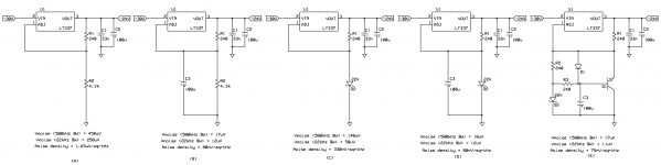
You might try the 10uF cap btn the adj pin and ground (and check Cout capacitance effect on noise with your load https://www.edn.com/electronics-blog...or-noise-floor
Here are my measurements (keep impedance of adj pin circuit low)
Attachments
- Status
- Not open for further replies.
- Home
- Member Areas
- The Lounge
- John Curl's Blowtorch preamplifier part III