I too have ordered a pair of 6.5 inch diam DVC drivers. i have extra PA here to modify
ActuaLLY, i have some huge subs for a long time and have not got them installed..... but they are huge and cost $2K USD each. 😱 If this works well, i will do it for those drivers also.
-RNM
ActuaLLY, i have some huge subs for a long time and have not got them installed..... but they are huge and cost $2K USD each. 😱 If this works well, i will do it for those drivers also.
-RNM
Last edited:
I was actually thinking about this idea when jn brought up the topic some time ago. The voicecoil is connected in series with a coil on the magnet, which directly opposes any flux change in the magnet itself. It wouldn't work very well with overhung coils however since the flux coupling constantly changes.
jneutron, what do you think?
Cutter heads use helium or N2 (I forgot which) to deal with heat. Overheating is really bad there with repair costs in the thousands and long lead times.I'm sorry...what means this phrase "is it worth going this far?"😕
What they really need to do is drill some holes in the pole piece and the return plate, and inject helium gas directly onto the voice coil. I recall IBM doing a scheme like that on some high power CPU modules. Apparently Helium has high heat capacity for it's viscosity...
Course, you'd need oxygen sensors in the room😉
jn
When I started in electronics, disk drives were moving from servo motors to voice coils for head positioning. The travel was 5 inches in milliseconds to microinch accuracy. However you could buy a house for they cost then. This was late 1960's technology. Amazing what real money can make possible and how clever those engineers were. The mainframes were still discrete. . .
discrete AND water cooled. I read a paper back in the 80s on how they made the ceramic blocks for the water cooled processors. You put the tracks on then fired the ceramic, which shrank 10% during firing. You can imagine what yields were like!
Oddly no one seems to want to return to single ended class A computing 🙂
Oddly no one seems to want to return to single ended class A computing 🙂
I was actually thinking about this idea when jn brought up the topic some time ago. The voicecoil is connected in series with a coil on the magnet, which directly opposes any flux change in the magnet itself. It wouldn't work very well with overhung coils however since the flux coupling constantly changes.
jneutron, what do you think?
Hermetic helium loudspeaker VC ??
Hmmm. oops . it's been done - Helium Bluetooth speakers powered by supercapacitors
OS
Oddly no one seems to want to return to single ended class A computing 🙂
Interesting how technology has lagged without being motivated by fear.
Cray used a very effective approach to cooling. They filled the whole system with Freon. Service was an issue but cooling was not.
people are experimenting with mineral oil cooling of servers again to get data centre densities up. Some reports suggest data centres will get to around 20% of global power consumption in a few years. Which is slightly unnerving.
Quite honestly, you have gotten it from the jump. No moss under you...I think I got that now and that's sure is where the beauty of your concept lies in... though I still can't exactly understand what it will do better that just plain current drive.
PS: The Goldwood drivers will need quite some time to ship to here... but I've found another nice 6.5" DVC easier to get here in Germany, the Monacor SPH-170tc and will order it, though quite a bit more costly but hopefully also a better design to start with.
So, that is three attempts at humor that I have failed miserably at..I meant, does the approach make a significant enough difference to justify the very high cost?
I suppose it does, if the user listens at a high SPL for a long period. But that is not a good practice in studios afaik. (The product is aimed at the studio segment.)
Centroid shift inward with frequency is a lowering inductance thing.jneutron, when you talk about the coil centroids expanding, is this the same thing you mean when you say inductance increases with the absolute velocity?
Is this different than the reluctance force described in that PDF?
I will have to work out the reluctance force thing, I suspect it's just a simple I dL/dt thing.
I build things that are in the most expensive real estate on the planet. Or, so I was told..Cutter heads use helium or N2 (I forgot which) to deal with heat. Overheating is really bad there with repair costs in the thousands and long lead times.
When I started in electronics, disk drives were moving from servo motors to voice coils for head positioning. The travel was 5 inches in milliseconds to microinch accuracy. However you could buy a house for they cost then. This was late 1960's technology. Amazing what real money can make possible and how clever those engineers were. The mainframes were still discrete. . .
Jn
Come on guys! What is the SPECIFIC circuit that JN is claiming will do what he claims? There are too many variations to quibble over. Which ONE is the RIGHT ONE?
So, that is three attempts at humor that I have failed miserably at..
Still doing better than me on that front 🙂
John, is that sufficient...or are there questions?
Jn
Tnt, thank you
It doesn't matter what anybody else on the planet thinks. Only me.So does everybody agree that the recent schematic put up by TNT is the right one?
It is my design, my understanding....
My neck.
Yes, that is exactly the design.
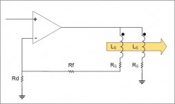
The connection by design, subtracts all magnetic linearities and non linearities between the drive coil and the pickup.
What is left is the resistive portion of the composite vc impedance.
It's almost constant current, but with two distinctions.
1. It sets the voltage across the real component of the vc impedance w/r to the input signal.
2. It zeros out all reactive components of the vc, both linear and non linear.
Jn
Oh, John.. You have to admit, that schematic proves that I am a really really good analog design engineer, just look at how complex that circuit is..man, I'm da bomb...😉
Oh, don't forget... Apparently, it needs some kinda "components" to actually work right...yah, details, details..😉
Last edited:
JN put it up. How can it be wrong?
Then there are the efforts to simulate it in spice and what may be a correct spice model. I'm sure something can be learned from that also.
I'm eager to see what 1audio and KSTR comes up with in their IRL efforts.
//
Then there are the efforts to simulate it in spice and what may be a correct spice model. I'm sure something can be learned from that also.
I'm eager to see what 1audio and KSTR comes up with in their IRL efforts.
//
Last edited:
Thank you TNT. Yes, there is a difference, however a dual voice coil would be a perfect way to make circuit C.
Sigh...Just making sure. Now what is the (if any) significant difference between this schematic and JN's? I refer to the schematic on the far right.
I have shown the Ls/Rs model for an inductor.
My config has the second "pickup" coil as capturing all the rate of change flux in the voice coils.
I show how my config subtracts all the magnetic linearities and non linearities from the feedback node, leaving only the real component of the vc end terminal..
Are you sayin that, you don't understand what we've been talking about, but yet you've still commented on it? Shame on you.
Jn
- Status
- Not open for further replies.
- Home
- Member Areas
- The Lounge
- John Curl's Blowtorch preamplifier part III