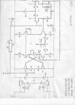
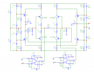
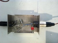
Another question was asked about the usefulness of the Hirata test. Well, in one case I found a real difference that I could fix. This was the so called 77studio board that I originally made for tape recorders and studio consoles. It had an AC balance (see cap in the middle of the board) that nulled the 2'nd to almost nothing. However, it also activated an error signal in the Hirata test when it was installed. Remove the cap, and the harmonic rose slightly, BUT the Hirata distortion disappeared.
Attachments
Ah. Interesting.
It appears to me that the balance trimmer is nulling differences between the Vaf AKA Early effect of the Jfet gate drivers.
Often in a circuit like this one of the Jfet gate drivers has a stiffer collector and the other collector just ends up being a useless load on the stage. But you can at least balance the asymmetrical Vafs. You could even use it to null the 2nd harmonic in all the other stages.
Depending on the transistors though it may have taken a lot of persuasion. The balance can drive one half up to 2x harder than the other.
It would be interesting to see a gain vs balance chart for the middle stage.
EDIT: The reference voltage at this point in the circuit is the positive rail, so C3 going to ground is a mistake. Maybe there was not enough ripple to matter, but maybe there was?
Last edited:
Another question was asked about the usefulness of the Hirata test. Well, in one case I found a real difference that I could fix. This was the so called 77studio board that I originally made for tape recorders and studio consoles. It had an AC balance (see cap in the middle of the board) that nulled the 2'nd to almost nothing. However, it also activated an error signal in the Hirata test when it was installed. Remove the cap, and the harmonic rose slightly, BUT the Hirata distortion disappeared.
Where was P3 set at?
One more time just for Derfy the !!!!
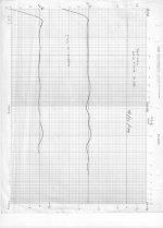
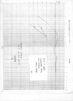
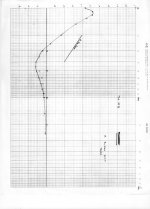
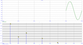
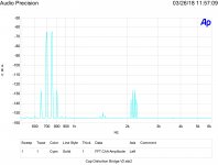
This is what I think is a revealing test IM from 700 & 750 hertz test tones at 10 VRMS combined.
Mouse over the thumbnail to see the label.
If Dimitri is in good form he might reveal why these results are so inportant!
This is what I think is a revealing test IM from 700 & 750 hertz test tones at 10 VRMS combined.
Mouse over the thumbnail to see the label.
If Dimitri is in good form he might reveal why these results are so inportant!
Attachments
-
 Wurth Electrolytic Series COG Cap 9 V bias 10K Series Resistor.jpg534.8 KB · Views: 106
 -
 Wurth Electrolytic With Series caps 5 uF NPO.jpg537.4 KB · Views: 124
 -
 Wurth 860010772005 Electrolytic No bias Mouser.jpg538 KB · Views: 125
 -
 IM TDK CGA5L2COGAH104J160AA 50V NPO 50 500 5000 10x 4,1 1,4.jpg424.2 KB · Views: 153
One more time just for Derfy the !!!!
This is what I think is a revealing test IM from 700 & 750 hertz test tones at 10 VRMS combined.
There's no useful information given with the plots, like what's the difference and where do you get these caps? I think I mentioned the Vishay line a week or so ago that Samuel measured for his thesis, do you want me to buy you a batch? They are not that expensive or audiophile at all, normal stock items that anyone can buy. In fact the values for an RIAA where it might matter are <$1.
You would appreciate this. I'm feeling a little flush today, in going through my father's effects I found 5oz of Pt that my sister might have junked.
Ed, it would be nice if you always shown test circuit, instruments used, values used. It would be a scientific method, then. As now, it reminds unspecified plots from marketing departments, rather than a scientific approach.
BTW that Groner thesis that Scott shown is excellent.
BTW that Groner thesis that Scott shown is excellent.
Mouse over the thumbnail. Standard 10 DUT setup.
You lost me, I meant part numbers.
In realm of listening at 'real levels' Musician wins landmark ruling over ruined hearing - BBC News What I don't get is that hearing loss in musicians is well known so why there were not offered ear protectors?
Sad as his career seems to be over and a reminder to those who want to listen at if they were in the midst of the music to be careful what they wish for!
Sad as his career seems to be over and a reminder to those who want to listen at if they were in the midst of the music to be careful what they wish for!
Parts description is visible if you scroll mouse over the thumbnail image.
Just too fast a clicker. I see electrolytics but the NPO is -130dB so what's the issue there are brands that do a little better and Vishay films that show virtually nothing.
BTW Ed, if you put one of the 1nV in amps at G =100 in front of the AP you can lower the noise floor as long as the ESR of the caps is low enough.
Last edited:
It also makes it impossible to digest on mobile, so I'll have to read this later. And x100 on having a schematic/part list in general.
Pavel,
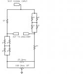
Same test rig I have used now for years and shown many times. AP System 2 XLR out and in. Generates 700 & 750 hertz equal parts combined to 10 VRMS. 10 Devices under test in a 4/1 and 1/4 bridge. I have almost a dozen different types to test.
Any signal applied to the devices should not appear at the output. However the limit to the null is the match of the devices. I use my GR bridge to sort the values and then assemble the best matched bridge I can from the values. Worst leakage of the test signal so far is - 60 dB from the test source. Unlike the resistor test shown there are no nulling pieces. Just selected capacitors. (Also note the triangle symbol at the bottom of the schematic is a balanced return not a ground.
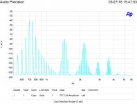
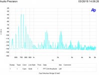
As can be seen from the electrolytics used in this test they get noisier from the small DC offset of the AP's oscillator. Not surprising as there is no control on if they are forward or reverse biased. Inserting the COG capacitors in series with the source signal drops the base noise level. Adding a bias voltage also changes the result. Next test is with a bias voltage higher than the peak signal voltage.
However what is shown so far does illustrate an issue that the electrolytic capacitors have passing an audio signal. (Hint it is not the distortion effects.)
Same test rig I have used now for years and shown many times. AP System 2 XLR out and in. Generates 700 & 750 hertz equal parts combined to 10 VRMS. 10 Devices under test in a 4/1 and 1/4 bridge. I have almost a dozen different types to test.
Any signal applied to the devices should not appear at the output. However the limit to the null is the match of the devices. I use my GR bridge to sort the values and then assemble the best matched bridge I can from the values. Worst leakage of the test signal so far is - 60 dB from the test source. Unlike the resistor test shown there are no nulling pieces. Just selected capacitors. (Also note the triangle symbol at the bottom of the schematic is a balanced return not a ground.
As can be seen from the electrolytics used in this test they get noisier from the small DC offset of the AP's oscillator. Not surprising as there is no control on if they are forward or reverse biased. Inserting the COG capacitors in series with the source signal drops the base noise level. Adding a bias voltage also changes the result. Next test is with a bias voltage higher than the peak signal voltage.
However what is shown so far does illustrate an issue that the electrolytic capacitors have passing an audio signal. (Hint it is not the distortion effects.)
Attachments
Last edited:
Time to return to Blowtorch, isn't it? Anything new, different or wrong with the attached circuit and plots? Maybe we might move on 😉.
Pavel why do you show the distortion in volts rather than in relative dBs? I always need to do mental gymnastics to convert the values to dB and it isn't very accurate either.
Jan
Jan, why do you show the distortion in relative dBs rather than volts?
I always need to do mental gymnastics to convert the values to volts,
and it isn't very accurate either........🙂
I always need to do mental gymnastics to convert the values to volts,
and it isn't very accurate either........🙂
Pavel why do you show the distortion in volts rather than in relative dBs? I always need to do mental gymnastics to convert the values to dB and it isn't very accurate either.
Jan
Jan, at least you have some mental training 😛. I'll be better next time.
This topology has much lower distortion for smaller signals like 1V. Anyone interested? I think we went through about 10 years ago. Time is passing quickly 😀.
- Status
- Not open for further replies.
- Home
- Member Areas
- The Lounge
- John Curl's Blowtorch preamplifier part III