Pavel,
Same test rig I have used now for years and shown many times. AP System 2 XLR out and in. Generates 700 & 750 hertz equal parts combined to 10 VRMS. 10 Devices under test in a 4/1 and 1/4 bridge. I have almost a dozen different types to test.
Any signal applied to the devices should not appear at the output. However the limit to the null is the match of the devices. I use my GR bridge to sort the values and then assemble the best matched bridge I can from the values. Worst leakage of the test signal so far is - 60 dB from the test source. Unlike the resistor test shown there are no nulling pieces. Just selected capacitors. (Also note the triangle symbol at the bottom of the schematic is a balanced return not a ground.
As can be seen from the electrolytics used in this test they get noisier from the small DC offset of the AP's oscillator. Not surprising as there is no control on if they are forward or reverse biased. Inserting the COG capacitors in series with the source signal drops the base noise level. Adding a bias voltage also changes the result. Next test is with a bias voltage higher than the peak signal voltage.
However what is shown so far does illustrate an issue that the electrolytic capacitors have passing an audio signal. (Hint it is not the distortion effects.)
Ed, do you think this phenomenon may reflect in a coupling capacitor loaded with high impedance to get sub Hz LF cut-off? Or is it just something "interesting"? Would you be able to evaluate influence to audio signal path when connected as a coupling capacitor? Would you be able to measure the effect in a real audio path then?
Pavel,
The devices under test effectively have no load on them as there should be no voltage across them! If you note the test box has a switchable load resistor. It has no effect on the results. So the issues shown will be present when used as a coupling capacitor.
The devices under test effectively have no load on them as there should be no voltage across them! If you note the test box has a switchable load resistor. It has no effect on the results. So the issues shown will be present when used as a coupling capacitor.
So next step is someone to repeat your measurement to verify your results. Analysis of cap imbalance?
Jan, why do you show the distortion in relative dBs rather than volts?
I always need to do mental gymnastics to convert the values to volts,
and it isn't very accurate either........🙂
Haha! Well, I think there's more of us than of you, so if you want the max number of reads and/or comments, better cater to the majority.
And for those sloppy readers among you who want to tell me that the majority isn't always right, I know that. That's why I wasn't saying that. Please reread my post ;-)
Jan
So next step is someone to repeat your measurement to verify your results. Analysis of cap imbalance?
First I should complete all of my tests. The comparison of the NPO vs Electrolytic is the first step in sensitivity analysis confirmation. The math for significance of capacitor unbalance so far tracks what the bridge is showing me.
Wheatstone bridge output vs balance was a first semester bit where and when I studied the subjects.
So the issues shown will be present when used as a coupling capacitor.
With or without the distortions, just curious my sound cards are full of them as coupling without the distortion. You don't need a bridge for noise effects, they aren't correlated.
With or without the distortions, just curious my sound cards are full of them as coupling without the distortion. You don't need a bridge for noise effects, they aren't correlated.
????? Is there supposed to be a correlation between your comments and the data I showed?
Ed, I agree there should be no output in case of perfectly same 10 devices. However, aren't you measuring only parasites?? And those series connected C//C + C//C ==> DA??
Wheatstone bridge output vs balance was a first semester bit where and when I studied the subjects.
Ed you missed my first point if you expand C as a polynomial function of V the first nonlinearity in V^2 is divided by 4 when you halve the voltage, V^3 by 8, and so forth.
If you carry out the series parallel scheme the limit is just two "perfect" reference caps against the DUT's. Talking about distortion only here.
????? Is there supposed to be a correlation between your comments and the data I showed?
Yes, I have lots of devices with electrolyic coupling caps that don't display distortions, no need for any agitation just curious. In your answer to Pavel you said there is no voltage across the DUT's but there is lots of AC voltage and displacement current in your bridge. You are extracting the worst case distortion. Pavel's point is that in an AC coupling application with care to make the time constant low enough there is no AC voltage only DC i.e. no mechanism to make distortion.
Last edited:
Pavel why do you show the distortion in volts rather than in relative dBs?
OK Jan, here is both for 1Vp output, quite realistic value. You can see that in case of "appropriate JFET hand matching selection" the distortion is vanishing low and only H3 for these smaller signals.
Attachments
It is troubling that Ed cannot get his measurements done, because he has to 'justify' everything that he does in making his measurements. Let's get real! ALL passive components have some residual distortion, and many passive components measure OK with normal audio measurements, but still have residual distortion that CAN be measured, IF you use the right test, OR the right test signal. We have known this for many, many decades. For example, back in 1977, I was perfectly happy with Mylar coupling caps. About the same time, a local engineer, from Lawrence Livermore Labs contributed a short LTE in 'The Audio Amateur' pointing out that DA is often not measured or even recognized in many capacitor types. However, it was only when someone complained about my use of a Mylar coupling cap, that I started to pay attention to DA. What this did ultimately was to get me started on using servos a few years later, when I realized that really good coupling caps were just too expensive and bulky to effectively use. Servos were cheaper and took less space. Still, even today, PMA fights for the use of Mylar coupling caps, and even challenges measurements of practical caps by other engineers. How can we go forward, when we are actually dropping back 40 years first?
And how can we go forward when someone permanently appreciates tube sound and vinyl sound (or even FM radio sound!), with all their audible! shortcomings, just for the nostalgia, sentimentality reason? I am quite old as well, but open to improvements brought by well done digital, which is IMO far better than any analog source. In a comparison with vinyl and tube shortcomings, mylar distortion is nothing.
Ed, I agree there should be no output in case of perfectly same 10 devices. However, aren't you measuring only parasites?? And those series connected C//C + C//C ==> DA??
If D/A is linear with voltage then it would not affect the results. But what would you suggest to isolate the DA contribution. It may well show up that capacitors with higher DA also measure worse.
What I think is being measured is any factor that is not linear with voltage.
I had enough experience with DA in capacitive dividers made from many serially connected capacitors. Unusable without parallel discharging resistors to define voltage distribution. But that time, 40 years ago, I did not care about non/linear behavior, but only about time response.
Well PMA, I am currently successful in making A rated audio designs. Perhaps you should learn something from this, rather than accuse me of some sort of bias. Of course, you can get away with double blind listening tests that will show that virtually everything that you make is OK, but I chose reviewer and customer listening feedback.
But what would you suggest to isolate the DA contribution.
John, Walt, and I did that decades ago with "surprise" a bridge measurement.
Yes, I have lots of devices with electrolyic coupling caps that don't display distortions, no need for any agitation just curious. In your answer to Pavel you said there is no voltage across the DUT's but there is lots of AC voltage and displacement current in your bridge. You are extracting the worst case distortion. Pavel's point is that in an AC coupling application with care to make the time constant low enough there is no AC voltage only DC i.e. no mechanism to make distortion.
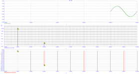
There should be no voltage out from the bridge of the devices under test. Any voltage should be due to mismatch between arms of the bridge. There is a certain maximum suppression that can be obtained due to the mismatch. With the COG capacitors this is a bit better than -80 dB. With the electrolytic capacitors shown this is a bit less than -60 dB.
Looking at the COG data the IM products are a bit better than -60 dB. From past use this is more than I would expect from the AP's internal generator, but a double check is certainly in order.
Now if you look at the electrolytic's harmonic distortions they are more than 90 dB down from the test signal and clearly not from the internal signal source. Fine for many measurement uses.
However they would still produce seriously bad artifacts that would clearly be perceptible listening to music. If you took musical tones of 75 and 125 hertz-ish and allowed them to produce a similar pattern of distortion and then did an audio weighting on the source and result you would have a signal to noise ratio of less than 45 dB.
It is not the DC component that makes the distortion. It makes the noise I suspect. Further testing is needed to confirm that. The DC component does change the distortion, but so far no large changes.
Following several threads of discussion here with interest.
John thanks for the comments on tape - very informative.. I'm going to inherit an Otari MX-5050 MKIII B2 very shortly so this got my attention.
The cap discussion is interesting, I have definite preferences, perhaps some of that is explained here. It is extremely relevant to XO and filter design where one cannot assume that there is no AC across the cap.
I don't have much useful to add, will keep following.
I had enough experience with DA in capacitive dividers made from many serially connected capacitors. Unusable without parallel discharging resistors to define voltage distribution. But that time, 40 years ago, I did not care about non/linear behavior, but only about time response.
Clearly you understand the importance of DA in high voltage circuits. The obvious proof is that you are still alive! There is the classic warning of the folks who were killed touching capacitors that had been discharged and then stored not shorted.
But the issue is there another way to discern which distortion components are due to DA versus other possible factors that are causing the residuals shown.
- Status
- Not open for further replies.
- Home
- Member Areas
- The Lounge
- John Curl's Blowtorch preamplifier part III