Ed, parasites will make the bridge mismatch. And no 2 capacitors (of same brand and type) would be the same. I am still not sure what this method would measure. For curiosity reason, I will probably try something.
Ed you missed my first point if you expand C as a polynomial function of V the first nonlinearity in V^2 is divided by 4 when you halve the voltage, V^3 by 8, and so forth.
If you carry out the series parallel scheme the limit is just two "perfect" reference caps against the DUT's. Talking about distortion only here.
Scott,
I think our difference here is the feel that dc/dt may not have the nonlinearities follow the same as your model. A large number of what may be modeled as mechanical issues.
Ed, parasites will make the bridge mismatch. And no 2 capacitors (of same brand and type) would be the same. I am still not sure what this method would measure. For curiosity reason, I will probably try something.
Yes there are always parasitics, stray inductances, random resistances etc. Part of why I am using 1 uF. Checking the capacitors on the bridge first also shows "D."
Can we at least agree that the electrolytic capacitors shown are not as close to ideal as the COG ceramics? 🙂
In realm of listening at 'real levels' Musician wins landmark ruling over ruined hearing - BBC News What I don't get is that hearing loss in musicians is well known so why there were not offered ear protectors?
Sad as his career seems to be over and a reminder to those who want to listen at if they were in the midst of the music to be careful what they wish for!
And the ROH have been ungracious in their response
Scott,
I think our difference here is the feel that dc/dt may not have the nonlinearities follow the same as your model. A large number of what may be modeled as mechanical issues.
Actually the internal mechanical issues are due to electrostatic attraction i.e. the voltage on the capacitor not external agency.
Can we at least agree that the electrolytic capacitors shown are not as close to ideal as the COG ceramics? 🙂
I never said I would use electrolytes in an audio signal path and I never did, with an exception of my very beginning with audio many decades ago.
There should be no voltage out from the bridge of the devices under test.
The voltage out of the bridge does not matter. There is substantial voltage across the arms of the bridge that makes the distortion. In an AC coupling application there is little or no AC voltage across the capacitor.
Absolutely clearly said. And impedance and parasitic mismatch makes the result that Ed is showing. Impossible to balance by the pot at the bottom.
I never said I would use electrolytes in an audio signal path and I never did, with an exception of my very beginning with audio many decades ago.
Nor did I, just trying to see if we agree on anything.
The voltage out of the bridge does not matter. There is substantial voltage across the arms of the bridge that makes the distortion. In an AC coupling application there is little or no AC voltage across the capacitor.
The voltage across the capacitor will of course depend on frequency. Size the value too low and you get all of the problems. But the experiment is to see the difference between types and manufacturers. It also is pointing out issues that were unclear to many.
Absolutely clearly said. And impedance and parasitic mismatch makes the result that Ed is showing. Impossible to balance by the pot at the bottom.
Pavel,
The schematic was for the resistor tests. There is no balancing adjustment with the capacitors. The balance is determined by matching the units on a bridge before testing.
Funny how the distortions change with capacitor types?
Ed, for capacitors, I expect you just replace 10 resistors with 10 capacitors. They see full voltage, then, thus absolutely different conditions than sees the coupling capacitor. Am I wrong and is your cap test bridge different? If yes, would you post it?
Ed, for capacitors, I expect you just replace 10 resistors with 10 capacitors. They see full voltage, then, thus absolutely different conditions than sees the coupling capacitor. Am I wrong and is your cap test bridge different? If yes, would you post it?
You got it, just the 10 resistors become capacitors.
As to the capacitor seeing voltage, with a 1 uF capacitor into a 10K load driven by a 75 and 125 hertz signal the weighted s/n would rise to 58 d/b for the electrolytic that you or I would not use. Raising the load to 100K gets you another 20 dB. still well below the dynamic range of a CD. It is that simplification from 10 volts to no volts doesn't look as good in dB with small volts.
Still looks like a big high quality or no capacitor is the better choice.
Now for those folks using an obsolete method of spinning almost flat vinyl mechanically encoded signal sources,the warp signal may indeed generate all sorts of low frequency noise issues with poorer quality capacitors.
1uF at 75Hz has 0 - j2122 ohm impedance, right? Not very low compared to 10k or even to 100k resistive.
Hopefully you know why I wanted to simulate this circuit before interpreting the results; there's a lot more going on under the hood and I wanted to know exactly what's being tested. The asymmetry between the components will have a pretty big effect on the results.
Rudely, my *real* job (that's a joke) has been consuming my brain power such that I haven't sat down in the evening to build a decent LTSpice model. Plus it'd be nice to bootstrap a monte-carlo onto this, but might be above my present pay grade. Y'all will be the first to know.
Rudely, my *real* job (that's a joke) has been consuming my brain power such that I haven't sat down in the evening to build a decent LTSpice model. Plus it'd be nice to bootstrap a monte-carlo onto this, but might be above my present pay grade. Y'all will be the first to know.
Nor did I, just trying to see if we agree on anything.
The voltage across the capacitor will of course depend on frequency.
In your bridge no it won't, all arms see 1/2 V at any frequency. You also keep forgetting the first nonlinear coefficient is V squared so you have to double your dB's. 10k to 100k load is 40dB not 20. I'm being lazy but this can all be simulated in SPICE just to keep the maths straight.
I'm a little shy of using math after the 200Hz FM'd by 2Hz actually has 2Hz content discussion.
Last edited:
BTW that Groner thesis that Scott shown is excellent.
http://www.nanovolt.ch/resources/low_distortion_oscillators/pdf/low_distortion_oscillator_design.pdf
Now for those folks using an obsolete method of spinning almost flat vinyl mechanically encoded signal sources, the warp signal may indeed generate all sorts of low frequency noise issues with poorer quality capacitors.
The subsonic signal around 10Hz due to cart/arm resonance can be anything btn 10 and 40dB below a reference 5 or 7cm/sec 1kHz test tone. The eccentricity and warp signals are some 50 to 70 dB below that reference tone (all after RIAA equalization)
And Thanks for the tests.🙂
George
And Thanks for the tests.🙂
Agreed entirely.
Anyone bringing data gets big ups from me (which really hasn't been me but trust me the stuff I generate isn't interesting 😀). And any criticism/controversy I might be bringing to the table is to make sure we understand what's being tested and how to interpret the results.
In your bridge no it won't, all arms see 1/2 V at any frequency. You also keep forgetting the first nonlinear coefficient is V squared so you have to double your dB's. 10k to 100k load is 40dB not 20. I'm being lazy but this can all be simulated in SPICE just to keep the maths straight.
I'm a little shy of using math after the 200Hz FM'd by 2Hz actually has 2Hz content discussion.
Are you really not following? You raised the issue that a capacitor used in a coupling application has less voltage across it. It does but it doesn't go to zero ever and rises with decreasing frequency.
Are you really confusing FM with AM?
Are you really confused that 20 log(10) is 20 not 40? We are talking about a fundamental not a harmonic.
Last edited:
Are you really confused that 20 log(10) is 20 not 40? We are talking about a fundamental not a harmonic.
Ed we're talking about distortion there are no new frequencies without a nonlinearity. If the fundamental is -20dB and the distortion goes as V squared the distortion is -40dB. Maybe you can clarify what other effects you are talking about I have never experienced any difficulty with noise even at the nV level coupling with electrolytic capacitors. Noise well below the cut off frequency is not of interest. As I said for s/n you don't need a bridge and setting up a low noise amp with input coupling would show an effect if any is there.
I'm usually only interested in the signal that I want not the one out of band.
As for AM and FM it does not matter a 200Hz carrier AM'd at 2Hz also does not have any 2Hz content. This was a discussion about the "sound" of DA and verged on Fourier denial, I can't be bothered to go back just forget it.
Last edited:
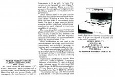
This is for John. 🙂So, 4 years later, in 1979, I threw away the analog electronics of a brand new A80, and designed new electronics. This was for Mobile Fidelity.
An ad from 'Recording engineer/producer' magazine December 1979 issue.
Attachments
Hopefully you know why I wanted to simulate this circuit before interpreting the results; there's a lot more going on under the hood and I wanted to know exactly what's being tested. The asymmetry between the components will have a pretty big effect on the results.
Daniel, I made some analysis, almost exactly 10 years ago, including asymmetry
Distortion in JFET input stage circuits
Today I would probably do more simulations, but as a start, I assume the page is still valid.
- Status
- Not open for further replies.
- Home
- Member Areas
- The Lounge
- John Curl's Blowtorch preamplifier part III