> Also lower Rout, even with Re added.
Yes . The channel resistance of the standard Hitachis is ~ 1 Ohm .
Yes . The channel resistance of the standard Hitachis is ~ 1 Ohm .
As usual, experience shape our preference, only a few has the resource to extensively explore multitude of available options.To me, better and more predictable linearity with bipolars, ...
Hi gpapag,
He qualified his use of feedback saying he only uses enough to reach the target specification for the amplifier he is designing. He isn't pro feedback as that was a qualified negative.
Post # 12983
-Chris
He qualified his use of feedback saying he only uses enough to reach the target specification for the amplifier he is designing. He isn't pro feedback as that was a qualified negative.
Post # 12983
It's just one comment he has made of many. I read that as he is forced to use negative feedback and would prefer to build products using no negative feedback.My approach is to make the OPEN LOOP performance as linear as practical, then applying just enough negative feedback to meet some spec in order to be competitive in the marketplace. More negative feedback usually means less optimum sound, in my experience.
-Chris
??
Indeed, one of the earliest NAD amplifiers, the 3020 had no emitter resistors and if the bias was not set carefully was prone to runaway and destruction. I had the (lack of) fortune to be working at a stereo repair shop which carried NAD in the early 1980s and fixed a metric s#!t ton of them. Although rated at 20 W into 8 ohms, we tested them at over 75 W into 2 ohms which was impressive for that point in time, and was the main attribute we used to explain their good sound quality..
But at the risk of losing any remaining credibility I may have here, I will tell you that amp was one of the very best sounding solid state amps as of 1983. We used to do what we called amp/speaker shootouts on Friday nights in the showroom. We carried Linn, Naim, Conrad-Johnson, M-L, Yamaha, NAD and used Quad, KEF and other speakers. That cheap ($125) little NAD amp was audibly the equal or better of just about anything in the store...for some reason. Despite so many design no-nos like input coupling caps, circuit breaker (in the feedback) and headphone jack normaling contact in the speaker line, etc. Many really high-end customers used to buy them just to use the amp sections... Go figure!
Here is the schematic :
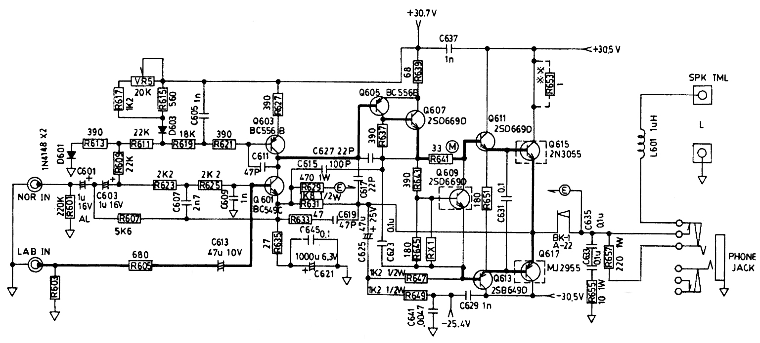
Maybe one of you geniuses have other explanations as to why that little amp worked so well? Perhaps peak current capability is one of the main determinants of perceived SQ?
Cheers!
Howie
John, regarding Re value. You are right, of course, that smaller would be better, from the point of view of crossover distortion and output stage transfer function linearity. The best Re = zero Re, however this is impossible due to thermal runaway. I find even Re = 0.1 quite dangerous regarding reliability, but still manageable. I use 0R22 as a compromise. 0R47 is too high speaking about output stage transfer function linearity. Your 0R15 might be an optimal compromise, if you can handle thermal runaway. I have designed a different thermal Vbe multiplier, NPN-PNP which works very well, for me. It could be seen yesterday in one of my posts. It is able to keep very stable Iq value, with temperature.
Indeed, one of the earliest NAD amplifiers, the 3020 had no emitter resistors and if the bias was not set carefully was prone to runaway and destruction. I had the (lack of) fortune to be working at a stereo repair shop which carried NAD in the early 1980s and fixed a metric s#!t ton of them. Although rated at 20 W into 8 ohms, we tested them at over 75 W into 2 ohms which was impressive for that point in time, and was the main attribute we used to explain their good sound quality..
But at the risk of losing any remaining credibility I may have here, I will tell you that amp was one of the very best sounding solid state amps as of 1983. We used to do what we called amp/speaker shootouts on Friday nights in the showroom. We carried Linn, Naim, Conrad-Johnson, M-L, Yamaha, NAD and used Quad, KEF and other speakers. That cheap ($125) little NAD amp was audibly the equal or better of just about anything in the store...for some reason. Despite so many design no-nos like input coupling caps, circuit breaker (in the feedback) and headphone jack normaling contact in the speaker line, etc. Many really high-end customers used to buy them just to use the amp sections... Go figure!
Here is the schematic :
Maybe one of you geniuses have other explanations as to why that little amp worked so well? Perhaps peak current capability is one of the main determinants of perceived SQ?
Cheers!
Howie
Guys, regardless what John has said, both A21 and JC1 are feedback designs and they have " standard" amount of FB. Not extremely high. I share the same design approach. First, the amp must be stable even into difficult load. Extremely high feedback is difficult to compensate for complex loads.
Hi Howie,
Yes, early designs were sometimes without any Re and prone to thermal runaway. Sweet sixties and seventies.
Yes, early designs were sometimes without any Re and prone to thermal runaway. Sweet sixties and seventies.
Indeed, one of the earliest NAD amplifiers, the 3020 had no emitter resistors and if the bias was not set carefully was prone to runaway and destruction.
I bought that and a pair of Magnepan MG1's for my father circa 1985.
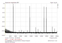
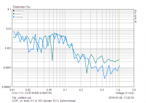
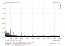
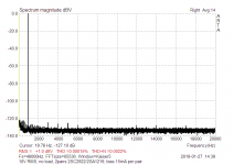
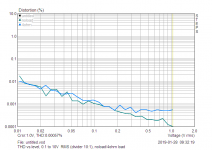
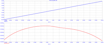
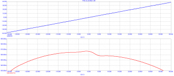
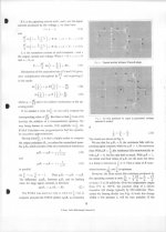
I did it different way, and what count counts are results. And results are strongly depending on output stage topology and compensation schematic. Attached are results for 3EF output stage,with 2 pairs output transistors, with output inclusive compensation (TMC). And bias only 15-20mA for one pair with Re =0,1R (two pairs used). So excess heat is not always inevitable.12.5W/4ohm, that would be quite normal, loud listening level. High bias, higher and high order harmonics negligible. This counts.
Attachments

0 Re is not optimum in any amp. The value depends on idle current. IF idle current is around .1A per device then 0.22 ohms is close to optimum If only 50 ma per device, then Re (opt) would be twice as much or 0.44 ohms etc. This was established by HP in 1971.
This comes from 26mV/Re law. However, if you simulate (and measure) EF push-pull power output stage, then the lowest Re, the lowest distortion.
26mV = kT/q
26mV = kT/q
Last edited:
This was established by HP in 1971.
It's not like you to go with conventional engineering.
That's BS Scott, I knew about Barry Oliver's article when it was first published.
PMA you are comparing apples to oranges. Higher quiescent current always makes the output more linear. Besides, Oliver's recommendation is fairly accurate with VOLTAGE DRIVE to the output devices. What do you estimate your drive impedance to the output devices is? Many serious designers add yet another complementary emitter follower pair to improve and lower the drive impedance to the output devices. We also have to factor in BETA NONLINEARITY when the drive impedance is relatively high, let's say above 20 ohms or so.
PMA you are comparing apples to oranges. Higher quiescent current always makes the output more linear. Besides, Oliver's recommendation is fairly accurate with VOLTAGE DRIVE to the output devices. What do you estimate your drive impedance to the output devices is? Many serious designers add yet another complementary emitter follower pair to improve and lower the drive impedance to the output devices. We also have to factor in BETA NONLINEARITY when the drive impedance is relatively high, let's say above 20 ohms or so.
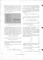

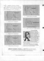
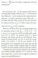
People always seem to forget that Barney Oliver's HP Journal paper actually says:
Screen capture from Oliver's paper attached.
_
1. The optimum value of voltage dropped across the emitter resistance is somewhere in the range 13mV to 26mV
2. However, due to the extreme difficulty of making the bias current accurately track the transistor junction temperature, the most practical solution is to set the voltage dropped across the emitter resistance to be many times (kT/q), i.e., many times 26mV, and rely on negative feedback to reduce the resulting distortion.
2. However, due to the extreme difficulty of making the bias current accurately track the transistor junction temperature, the most practical solution is to set the voltage dropped across the emitter resistance to be many times (kT/q), i.e., many times 26mV, and rely on negative feedback to reduce the resulting distortion.
Screen capture from Oliver's paper attached.
_
Attachments
Screen capture from Oliver's paper attached.
Yes as I remember it, pointed out before to no avail just like Ron Quan's results that no modern IC's on high speed processes had any measurable PIM (except maybe micro-power circuits).
As I showed yesterday a 500mA biased output with 110mV on Re would need no feedback up to 25W or so.
We're on orbit 48 with this stuff best to find something new.
Last edited:
As long as you stay in Class A, then the emitter value does not matter. However, it is almost impossible to stay Class A. 1/2A gives 4W Class A, 1A gives 16W Class A, and 2A gives 64W Class A all into 8 ohms. Now everybody select your standing current that you want, then multiply by two times the DC voltage per side, and you get how big your heatsink has to be.
Mark, I am surprised at you. You are lazier than I thought. '-) Why not do it RIGHT and just add alternate temp tracking? That is how I do, and I have thousands of products out there that don't go into thermal runaway.
Actually my FIRST amp, the one that Scott and Nelson has actually seen, used a 1ohm emitter with 0.5A bias. When it was independently tested the technician (still a friend of mine) noted that it did not go into class B transistion nicely, and I had 40 dB of feedback. That is WHY I consider Barney's article so important. He analyzed and got us a guide to DO IT RIGHT! That is what separates the men from the boys. '-)
Actually my FIRST amp, the one that Scott and Nelson has actually seen, used a 1ohm emitter with 0.5A bias. When it was independently tested the technician (still a friend of mine) noted that it did not go into class B transistion nicely, and I had 40 dB of feedback. That is WHY I consider Barney's article so important. He analyzed and got us a guide to DO IT RIGHT! That is what separates the men from the boys. '-)
Hmmmm. I dont see any of this as SOTA any more. SOTA amps can all produce bearely measurable HD/IM . They use Error Feedback Correction.
Several easy to implement topologies are presented by Dr. Arto Kolinumml ... Audio Power Amplifiers.
We should try them as mods to any existing amps to see the before and after results.
THx-RNMarsh
Several easy to implement topologies are presented by Dr. Arto Kolinumml ... Audio Power Amplifiers.
We should try them as mods to any existing amps to see the before and after results.
THx-RNMarsh
- Status
- Not open for further replies.
- Home
- Member Areas
- The Lounge
- John Curl's Blowtorch preamplifier part III