Oh, now I see.
You already have my Spice files.
How else can I help ? PCBs ?
I am using 2SK372s for all the NJFETs, which is essentially 2x 2SK170 in parallel.
Do have some if you need them, but not unlimited.
Of course one can also solder 2x 2SK170 // top and bottom of the PCB instead.
Patrick
about 150,000 available starting at 1 dollar each.
2SK372 Price & Stock | DigiPart
THx-RNMarsh
Joe, the one distortion you have not shown to support your claim is the measured distortion of the acoustic output. Distortion correlation of amplifier voltage and current to speaker acoustic output for both "common" speaker and your "improved" needs to be established by measurement, not enough by your saying so.You realise that an amplifier can have two different sets of harmonic distortions, one for voltage and another for current when connected to a load that is ...
DVC drivers with bifilar VC wire have a nice use case in a balanced Birt bridge to extract the microphonic voltage ("back-EMF") which is a velocitity signal (in order to build a control loop with it). The Birt brigde uses a servo to adjust one leg of the bridge to servo out "DC" resistance changes of the VC (thermally induced). With a DVC driver the input voltage to this servo is already pretty much free of AC components, no need to filter the signal big time, a real advantage especially when long time constants would be needed otherwise. Output of the control loop amp should be current in order to revert to current drive once loop gain drops below 0dB.
Of course, like any bridge it lives of off the perfect matching of the bridge which is the hard/impossible part when the static VC impedance isn't constant (vs. excursion). Using the VC as its own velocity sensor also is compromised as soon as BL(x) isn't constant anymore, or anything that affects induced motional voltage for that matter. Overload behaviour must be well checked, the might be a lot of cone movement overshoot. Underhung VC works best, low eddy currents as well (slotted pole-piece etc), and avoid excursion overload. @Soundbloke told us, before....
Of course, like any bridge it lives of off the perfect matching of the bridge which is the hard/impossible part when the static VC impedance isn't constant (vs. excursion). Using the VC as its own velocity sensor also is compromised as soon as BL(x) isn't constant anymore, or anything that affects induced motional voltage for that matter. Overload behaviour must be well checked, the might be a lot of cone movement overshoot. Underhung VC works best, low eddy currents as well (slotted pole-piece etc), and avoid excursion overload. @Soundbloke told us, before....
Last edited:
Right now with my MI 15dB is more than enough, I need you to help with all the fancy $$$ carts. 🙂
As I'm planning to (at some point) build a fairly std Demrow INA for MC use (and none of my MC are high dollar) this is interesting. I had noted the std circuit starts running into problems as you drop the gain below 40dB, so had never considered it could be modified to run all the way down to line stage gain levels.
Of course being an idiot I am on the lookout for silly low output MCs cheap just to give me an excuse to chase daft low noise down the rabbit hole for fun 😛
I find it very difficult to understand technically what you have from your explanations. Seems to me that you assume correlation not yet established by measurement. The more I read your posts, the more uncertain I am of what it is that you have. I am unable to infer what sonic benefit your "improvement" bring to the table. Hopefully measurement will shed better light on what you do have.🙂
If it is truly not possible then nobody will achieve it. That does not mean that nobody will believe they have achieved it.Joe Rasmussen said:But my own ambition and what I strive for is to get virtually the same benefits from voltage drive that can be had with current drive. There will be some that will say that is not possible, in which case they will never achieve it. But I believe it can be done
As others have said, you can put any impedance you like across a voltage source and it remains a voltage source so anything else connected to it will not see any difference. The voltage source will see a different amount of current drawn, but that is then a voltage source (i.e. amplifier) issue not a load (i.e. speaker) issue.
I find that hard to believe. You have not only equalised the impedance but also the acoustic response? Can I guess that it makes the speaker very low in efficiency?If the end result is not good as hoped for, I will still have figured out this: You can cancel out the output impedance of an amplifier and make the speaker compatible with both voltage and current drive. THAT has already been achieved and a good thing! I have speakers here that can already do that and have amplifiers with output impedances between 0.1 Ohm and 270 Ohm. It locks in the crossover, it locks in the bass alignment. This is not theory, but is a physical fact.
Poor use of language inhibits the conveying of meaning. Muddled writing can sometimes be a sign of muddled thinking. Physics is not like social norms; you can violate social norms; the best you can do with physics is kid yourself that you have violated it.I will leave the language for others, my job is to convey, not to be 'politically correct' as they say.
Why is it always 'jam tomorrow' with these people? Max Headroom is the same; always promising, never delivering.Oh, the measurements I spoke about, they will be very disciplined and tightly documented.
No. Have you heard of a circuit called a potential divider?Max Headroom said:And further to this, as Joe says a fully compensated loudspeaker (appears as ohmic load) will not care a hoot about amplifier output impedance/damping, including amplifier frequency dependent output impedance variation
Only if the cable is rather long.Resistance termination of speaker cable at each end also improves overall clarity and dynamic noise floor, cheap quick and easy.
Are you trying to say that an amplifier may have a nonlinear output impedance? If so, why not simply say so? This is well known, although in most cases if the impedance is small enough it doesn't matter too much how nonlinear it is. Why is it that whenever you think of something which happens to be true you always assume that nobody else has ever thought of it before? By the way, a nonlinear output impedance will give different 'current' and 'voltage' distortion (as you confusingly put it) into a resistive load too. Something an amplifier cannot have is two different output impedances at the same time.Joe Rasmussen said:You realise that an amplifier can have two different sets of harmonic distortions, one for voltage and another for current when connected to a load that is not purely resistive? Maybe that sounds too 'heretical' for some and does not sound politically correct, because they never thought that possible?
This appears to be an acceptance that the idea (I had better not call it a 'claim'!) on which the whole thing hinges has not yet been demonstrated, just that Joe is very confident that when he finally gets around to doing the tests he will be proved right. I will not hold my breath.I will want to prove that there will be a precise correlation between the harmonic distortion that appears on the current side and that picked up by a microphone, because the driver is a current device, that is what needs to happen and pretty sure it will. But no claims yet, as I am actually very conservative about making claims - only that I am being positive about it and feeling good about it. But don't tell me I am making claims, I haven't as yet quite done that.
More like this :Like this?
Is the name still correct? It seems it feedbacks more/else than the location/motion?
//
Attachments
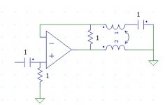
Exactly like that. And yes, the name was not accurate.Like this?
Is the name still correct? It seems it feedbacks more/else than the location/motion?
//
DVC drivers with bifilar VC wire have a nice use case in a balanced Birt bridge to extract the microphonic voltage ("back-EMF") which is a velocitity signal (in order to build a control loop with it). The Birt brigde uses a servo to adjust one leg of the bridge to servo out "DC" resistance changes of the VC (thermally induced). With a DVC driver the input voltage to this servo is already pretty much free of AC components, no need to filter the signal big time, a real advantage especially when long time constants would be needed otherwise. Output of the control loop amp should be current in order to revert to current drive once loop gain drops below 0dB.
Of course, like any bridge it lives of off the perfect matching of the bridge which is the hard/impossible part when the static VC impedance isn't constant (vs. excursion). Using the VC as its own velocity sensor also is compromised as soon as BL(x) isn't constant anymore, or anything that affects induced motional voltage for that matter. Overload behaviour must be well checked, the might be a lot of cone movement overshoot. Underhung VC works best, low eddy currents as well (slotted pole-piece etc), and avoid excursion overload. @Soundbloke told us, before....
This is not being used to extract the velocity signal. Because, inductive non linearities will distort the velocity signal being measured.
Rather, this is subtracting all reactance components directly at the transducer geometrically, leaving only the real component. It's better than trying to use a DSP to get the real part, as calculations would require knowing the history of motion to calculate the non linearities. Using the second vc, the calculations are already done for you in real time as is the subtraction.
I suspect this setup will flatten the speaker response as well as flatten the phase, in addition to lowering distortion.
Worth a try, no?
jn
ps. In essence, it it trying to make the real component of the speaker an accurate duplicate of the input signal. It really is a current drive signal, but it ignores the non linearities of the vc transfer function. In a pure current drive, there is no accounting for the non linearities, the assumption is that all the current is being used to push the vc by BLI. When the vc inductance is changing, that inductance has to be charged so will steal some of the energy as inductance rises, and gets it back when the inductance drops...you know, the second part of E = LdI/dt + I dL/dt. It is that varying inductance that modulates the vc force, and the second coil actually reads that changing inductance because it is coupled intimately to the time varying flux component responsible for that portion.
On the plus side, you can look at exactly what the amplifier needs to drive the speaker. It should be distorted while the acoustic output is not.
(well, that's the theory anyway..). This setup is my version of KISS...keep it simple stupid. If you can do this without dsp or fancy circuits like those mechanical engineer guys did, but get even better results, it is a success.
Last edited:
If it is truly not possible then nobody will achieve it. That does not mean that nobody will believe they have achieved it.
True, but has the Fat Lady already sung? We shall see.
I have something in mind, I have alluded in the past week what it is, and if some had taken it seriously they might have figured out what it is.
There are two possible outcomes and I am either right or wrong. So be it, I have no delusions, only hope based on something that points in that direction.
But it has to be tried, it has to be tested, and it will stand or it will not.
That is how science works.
Scientists don't usually keep alluding to something they have in mind; they either declare it so others can pick it to pieces or they keep quiet until they have some evidence or coherent theory. That is how science works.
Don't expect us to figure out what you have in mind; to do that we would have to share your assumptions and understanding and it is clear that we do not. So far, to the extent that you have revealed your thinking, we have said that you are mistaken - in some cases seriously mistaken i.e. newbie level mistaken.
Don't expect us to figure out what you have in mind; to do that we would have to share your assumptions and understanding and it is clear that we do not. So far, to the extent that you have revealed your thinking, we have said that you are mistaken - in some cases seriously mistaken i.e. newbie level mistaken.
Joe, the one distortion you have not shown to support your claim is the measured distortion of the acoustic output...
I know that. That is why it is not yet a claim and I have deliberately avoided using that word. Have you not noticed? I am simply making the point that I am exploring something that has intrigued me. Whether it turns out I have already spelled out is provable by a measurement(s) that I am working on. You should already know that such a structured measurement is not easy-peasy. So please do not accuse me of something I am not guilty of. Take that last comment as dry humour. Some of that is sorely lacking here. Also, I have an enthusiastic nature that does not seem to fit well with some and very well with others. So be it.
Distortion correlation of amplifier voltage and current to speaker acoustic output for both "common" speaker and your "improved" needs to be established by measurement, not enough by your saying so.
That sounds even more confusing than anything I have stated so far. So I can't comment on that.
Lighten up! At least I am the one sticking my neck out. But what I am doing, in consultation with people that I consider more smart than I am, is to test something, submit it for scrutiny. But can you blame me if I limit this to about twenty-something people, several scientists, a number off EE's (did Scott note I said 'EE' here... some levity please 🙂), loudspeaker designers and theorists/academics. I have had nothing but encouragement. That fuels me.
Why is it that on www.diyaudio.com there is no more an appetite to explore?
Oh, and finally before I go to bed, there is an inclination here by some to paint me as technically antiestablishmentarian.
I am anything but that - and my extensive list of friends proves that!
But they avoid this space like the plague and they wonder why I even bother? Maybe because I used to love what these forums used to be like and what Jason did back then was a really a good thing. Many that used to be here are no longer. I could mention names, that have kept in contact in other ways. That is sad. And no, this is not an anti-moderator statement either. Some have privately been supportive.
Off to a better place, gotta get my beauty sleep.
Scientists don't usually keep alluding to something they have in mind...
You kidding me? They do that all the time. Get rid of that metal straight-jacket. Science is a battle of ideas, you should know that!
Zzzzz.....
But Joe, you have wasted thousands of words and we have yet to see an idea from you. Just words so far.
But the ideas have to be proven and if there is an experimental result, it must be verified by repeating the same experiment in another independent lab. Then it can be considered verified. This is the science, not just some crazy ideas.
Joe,
Take what I have just done here as an example of what to do.
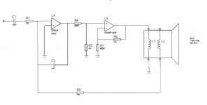
I have provided a clear and concise explanation of the effect I have been discussing. I have detailed what to look for, provided equations, and we now have a basic schematic to use to test it courtesy of Richard and TNT.
I have also discussed what the circuit will do, and how it works.
Everybody here has the opportunity to discuss the technicals, pick it apart, beef it up, discuss the intricacies and the downfalls. In short, brainstorming as well as peer review.
In addition, hardware can be built to test and either verify or refute what I have presented. I will be proven right, or proven wrong.
THAT is how it works.
What you've been doing here does not rise to that level. I get the feeling that you are just trying to sell something.
In addition, your verbiage has been rather shall we say, "non technical".
Jn
Take what I have just done here as an example of what to do.
I have provided a clear and concise explanation of the effect I have been discussing. I have detailed what to look for, provided equations, and we now have a basic schematic to use to test it courtesy of Richard and TNT.
I have also discussed what the circuit will do, and how it works.
Everybody here has the opportunity to discuss the technicals, pick it apart, beef it up, discuss the intricacies and the downfalls. In short, brainstorming as well as peer review.
In addition, hardware can be built to test and either verify or refute what I have presented. I will be proven right, or proven wrong.
THAT is how it works.
What you've been doing here does not rise to that level. I get the feeling that you are just trying to sell something.
In addition, your verbiage has been rather shall we say, "non technical".
Jn
For any Wilson audio lovers in the santa monica area
The Audio Salon Santa Monica Hosts WATT/PUPPY Family Reunion December 5th | Analog Planet
I have to say that's something I would go to if I could get a ticket just to listen to how much (if much at all) things have changed over the years.
The Audio Salon Santa Monica Hosts WATT/PUPPY Family Reunion December 5th | Analog Planet
I have to say that's something I would go to if I could get a ticket just to listen to how much (if much at all) things have changed over the years.
No, just technically wrong/mistaken/confused. Of course, if you have evidence that audio circuits do not work according to the low frequency approximation of Maxwell's equations (usually known as circuit theory) then you should show us and await your Nobel prize.Joe Rasmussen said:Oh, and finally before I go to bed, there is an inclination here by some to paint me as technically antiestablishmentarian.
Your experience of doing international level peer-reviewed science and engineering must be different from mine. Granted, I only have about half a dozen academic research journal articles to my name, having spent most of my career in industry; maybe you have more extensive experience?You kidding me? They do that all the time. Get rid of that metal straight-jacket. Science is a battle of ideas, you should know that!
- Status
- Not open for further replies.
- Home
- Member Areas
- The Lounge
- John Curl's Blowtorch preamplifier part III