Anatech, OF COURSE, AMPEX had first claim to these circuits, IF they wanted to use them. I showed them everything in 1978, BUT they didn't want to use them. Transformers were good enough for low noise for them! The complementary differential input was too complicated and expensive (at the time) for them to bother with also. In 1969, I built a 2000+ W motor drive power amp for Ampex Research that used the complementary differential input stage, but they decided not to build it because it was too complex as well. Today we can easily make them like I did in 1969, and sometimes we do.
John..., you enjoy doing on this thread is blindly encouraging anyone who antagonizes a few individuals...
They antagonise themselves!
BTW, I meant mental straight-jacket earlier on.
How do you get beyond text book language (anybody can pick up one of those) and make people think in different ways? You have to use language to extend language. But then you guys get all threatened?
What was that Max Planck said? Something about theories not dying, only those who hold them eventually do?
Let me quote a fellow Dane who must have been a little crazy:
“An expert is a person who has made all the mistakes that can be made in a very narrow field.”
“The opposite of a correct statement is a false statement. But the opposite of a profound truth may well be another profound truth.”
“Prediction is very difficult, especially about the future.”
“There are some things so serious that you have to laugh at them.”
“How wonderful that we have met with a paradox. Now we have some hope of making progress.”
“Everything we call real is made of things that cannot be regarded as real.”
“No, no, you're not thinking; you're just being logical.”
“Never express yourself more clearly than you are able to think”
Food for thought?
I mentioned an early 1966 article in 'Electronics Letters' that got me on track. The engineer of course made such circuits for the military, but he gave no examples.
Attachments
Last edited:
I can't agree with that. Yes, the final product can be significantly different, but the physics, science, and engineering are the same.Sure. That's a very different line of work. Not much relation to most audio design. We could use much better dacs for very low cost, though...
While designing the wiring of a very large machine where Yankee stadium can fit in the center is not the same as wiring a preamp, the ground loop science is.
In the specific case of the dual voice coil tech I've been discussing here, it certainly has little to do with a 35 foot tall 14 foot wide superconducting solenoid sitting in the center of a million ampere plasma that initiates. But as has been seen, the e/m understanding is the same, just scaled differently.
Nobody in the audio world would ever know about the technique I designed for the fusion guys if I hadn't realized it could apply to speakers. Heck, it might even be possible that I used a technique that some subwoofer person devised a decade ago and I just happen to apply the same technique to detect the quench of a fusion component.
As I said, I bet there are plenty of solutions out there just begging for a problem to solve.
But standing on the side of the road yelling to the truck drivers that I was great (50 years ago), well. Fairly sad.
Jn
Ps. Yes, the parrot skit..😀
Last edited:
So you knew that there was a physical limit to noise (at a certain impedance) but also that the transistor technology was not yet available to reach your target. But you monitored the development and finally made it. Now, to break physical laws is a bit different. No research, persistence or urge will make that happen. Well, one can wait for the next big-bang - maybe something will come up there 🙂
//
//
Last edited:
So you knew that there was a physical limit to noise (at a certain impedance) but also that the transistor technology was not yet available to reach your target. But you monitored the development and finally made it. Now, to break physical laws is a bit different. No research, persistence or urge will make that happen.
NOBODY IS SUGGESTING BREAKING ANY PHYSICAL LAWS!
Monitor development?
Absolutely!
Research?
Absolutely!
Persistence?
Absolutely!
Extreme persistence in opposition to slurs?
ABSOLUTELY!
That is real science for you, done in real time.
Quite honestly, your technical descriptions ( when you are not diverting or attacking) do indeed lead all to believe you have no understanding.
If you could give a clear and concise detailed explanation as to what you are thinking of, that would be a good step forward.
In addition, I would like a clear and concise explanation as to how any device placed on the output terminals can affect the voice coil current.
Jn
If you could give a clear and concise detailed explanation as to what you are thinking of, that would be a good step forward.
In addition, I would like a clear and concise explanation as to how any device placed on the output terminals can affect the voice coil current.
Jn
Actually, he said he visited ortophon first, went to work for Ampex later that year. So I would argue John's side on this one..One question comes to mind. Since you were employed at Ampex, and you did use their equipment and lab time to invent this. Don't they own the rights to that invention of yours? It seems directly applicable to their core business, and probably you failed to disclose your invention per the terms of most employment contracts. When I worked at the cal lab, any invention I came up with during that time frame would belong to Transcat. Good thing I didn't have any insights during that time.
You might have dodged a bullet there for years John.
-Chris
Jn
I mentioned an early 1966 article in 'Electronics Letters' that got me on track. The engineer of course made such circuits for the military, but he gave no examples.
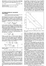
Nice reference though he cites even earlier work. If you looked hard enough you could probably find some references from WWII radar work in combining correlated signals with amplifiers having uncorrelated noise. The basic principle of paralleling n amplifiers to get square root of n noise is very old (I'm referring to this basic principle not any of your other work).
More like this :
That is not what I was thinking. TNT had it correct.
My intent was to not load down the second coil nor spoil the feedback with any of the output drive signal.
Jn
JN - your proposition described merits seem to be very attractive. Hasn't anyone done this? Thats an patent right there - darn; you post became prior art 🙁
Motion feedback with an accelerometer seems limited in comparison...
//
Motion feedback with an accelerometer seems limited in comparison...
//
Last edited:
I mentioned an early 1966 article in 'Electronics Letters' that got me on track. The engineer of course made such circuits for the military, but he gave no examples.
Even when you give PLENTY of examples, you cannot win, and I have given PLENTY.
Your story re 2N4401/2N4403, yep, if somebody says it is impossible, they will never do it. There are many examples of this - and I have my own little collection of them.
Please endulge me and use this opportunity to show them that this is more than just words and I have laid out highly specific things that they just unfairly ignore (but others have taken very carefully note, just not here).
I was told that it was impossible to design and drive a mulit-way loudspeaker from any source impedance, where it did not matter whether the amplifier is voltage or current.
Of course I was told that was not possible.
Voltage source is low Z, but it relinquishes all control of the current. The current source is high Z, but relinquishes all control of the voltage. So you must control the voltage, that is the prevalent/dominant view, thou shall not have any doubt, OK?
What about always controlling the current, the Madman asks?
But certain things, past and present, ideas were percolating and indicated that just maybe it could be done. Would it be worth pursuing it? Absolutely!
So, we know the type of amplifier used is down to a single value, the output impedance of the amplifier. The box alignment and the crossover is dependant on having a low source impedance, or at least a known impedance and you should stick to that. This was set in cement!
I disagreed!
Something told me that need not be the case, not at all. Something told me that the idea was fixed because the voltage model is all pervasive when it comes to dynamic loudspeakers.
Yet they are current devices!
Menno Vanderveen, I was told by one of his students a few weeks back face-to-face, Menno told his class that voltage is easy, current is not. So everything gravitates to voltage - but it does not tell the complete story when it comes to dynamic drivers and how crossovers works. (No, voltage is not the enemy either).
So when I bring it up, all I get is lip service that current is sorta correct, but... then they revert to voltage ALL the time. It is a mental barrier.
So I thought, what if we actually find out what the current is doing in loudspeakers and then I found something out that goes back five decades and something Neville Thiele did - he used constant current (not exactly the same as current drive) to derive the impedance plot of the driver.
The voltage under those circumstances becomes proportional to the impedance. But the impedance is actually not about the voltage at all, an impedance is about how current is impeded and that the voltage here is proportional to the current. So an impedance graph of a driver that we have all seen, is not about the voltage at all. It is about how it impedes current, that is why we call it an impedance. There is no mention of voltage in an impedance graph.
Then it also dawned on me, the impedance above the Re DC resistance of the voice coil, this is the so-called reactive part of the impedance, produces a zero degree current phase angle when the source impedance is high enough.
BINGO!
It just hit me...
Make the amplifier produce the same current at all frequencies!
You just cancelled out the output impedance.
Try it. It keeps the current phase angle the same throughout - and you no longer rely on the output impedance to control the box alignment and the crossover.
If they want examples, I would love to! Talk about how it works and about how this is about thinking current rather than voltage? Again I would love to. I do it offline all the time, but online is verboten. That is crazy!
Here is how I did it, just look below, they can study how it was done:
Voltage source:
Current source:
Overlay comparison, Green is voltage and Red is current:
Below is a crossover that suppresses the back-EMF impedance of the individual drivers and how then the current is EQ'd as seen directly by the amplifier output terminals.
The heart of it and how it was done - FULLY PUBLISHED:
Guys, why can I have this discussion offline, but not online?
.
Oh well...😉JN - your proposition described merits seem to be very attractive. Hasn't anyone done this? Thats an patent right there - darn; you post became prior art 🙁
//
I guess I'm not here for fortune.
Jn
Hi Jneutron,
I`m not on a witch hunt here. Just looking at the question of lab capabilities and John`s access to the equipment needed to develop low noise circuits along with the claim that he invented this circuit configuration. I have trouble imagining anyone without access to this equipment developing this in their basement or garage. John has claimed he did not work this out in his garage - which I would believe.
My own education and development has been completely on my own without equipment that did not belong to me. Early on I recognised that good equipment, and a lot of reading, is required in order to develop anything of use to the audio community. The existence of simulators side steps this to some degree, but you eventually must create something for proof of concept at least. We are back to having good equipment. This explains my bench, even though it is comprised of ancient equipment, save the RTX and computer / software combination.
-Chris
Yes, timing is important of course. But I still imagine that work on this was done on Ampex`s time and equipment. John, you say you offered this to Ampex in 1978, a decade after you started to use this in your own career shortly after you came up with the circuit concept.Actually, he said he visited ortophon first, went to work for Ampex later that year. So I would argue John's side on this one..
I`m not on a witch hunt here. Just looking at the question of lab capabilities and John`s access to the equipment needed to develop low noise circuits along with the claim that he invented this circuit configuration. I have trouble imagining anyone without access to this equipment developing this in their basement or garage. John has claimed he did not work this out in his garage - which I would believe.
My own education and development has been completely on my own without equipment that did not belong to me. Early on I recognised that good equipment, and a lot of reading, is required in order to develop anything of use to the audio community. The existence of simulators side steps this to some degree, but you eventually must create something for proof of concept at least. We are back to having good equipment. This explains my bench, even though it is comprised of ancient equipment, save the RTX and computer / software combination.
-Chris
Quite honestly, your technical descriptions ( when you are not diverting or attacking...
That is a weird thing to say.
You guys are the one ganging up on me and tearing down anything I say without any considered thought. Please read my last detailed post, and please don't say it contains diversions. Diversions is something you guys are good at as well.
It is not my comfort zone that seems threatened here. It is clearly yours. Why?
I think that needs an explanation.
So this is a big advertising campaign for your Elisnore speaker and the fuzz is about a 13 Hz band centered around 18 Hz for 2 dB, 30 dB down?
//
//
So, this is a simulation only. And it is single frequency simulation. What happens with actual music?
While the graphs say spl, is that simulated spl?
I notice the sim has 5 db dips, is that good?
What is the distortion like? Your point was distortion stuff, right?
Also, what about transient response?
Jn
While the graphs say spl, is that simulated spl?
I notice the sim has 5 db dips, is that good?
What is the distortion like? Your point was distortion stuff, right?
Also, what about transient response?
Jn
No, it is not. Your technical explanations have been confused, so much so that absolutely nobody sees consistency.That is a weird thing to say.
I have been trying my best to consider what you've posted, but you have posted such a mishmash of incorrect EE theory that has been pretty much useless.You guys are the one ganging up on me and tearing down anything I say without any considered thought. Please read my last detailed post, and please don't say it contains diversions. Diversions is something you guys are good at as well.
Oops, back to diversion and attack? You almost made it through an entire post without that.It is not my comfort zone that seems threatened here. It is clearly yours. Why?
My personal comfort zone with EE as well as E/M theory is significantly beyond anything you can understand. Primarily from experience, not necessarily IQ...😉
Show us actual plots of distortion, phase, and waterfalls, that's simple stuff nowadays.
Ps..Elsinore speaker? Is all your posting on this simply trying to sell product?
That would explain your approach.. Victim, conspiracy theory, martyr...
I wish you luck with your product line. However, I recommend you get a technical writer that understands circuit theory, you are not good with that. And playing the victim, I suspect that as a marketing tool, it's rather limited.
Jn
Do the wiring diagram incl. notes in the 4th picture describe a physicalrealisation that measures as in picture 1-3?
//
//
So this is a big advertising campaign for your Elisnore speaker and the fuzz is about a 13 Hz band centered around 18 Hz for 2 dB, 30 dB down?
That is a low blow. I have not made money from the Elsinore DIY Project. I have made a huge loss and everybody who has been involved in the Elsinore Project knows that. I don't make money from DIY, only made losses. The gains have been elsewhere, like a lot of friends that make life better.
Please, would you reconsider what you just said? It was not nice.
Re the 18 Hertz deviation under current drive versus voltage drive, may I respectfully ask if we could have a respectful interchange about that.
I would very much appreciate it. The blip only occurs when the box is vented. It does not exist when sealed or aperiodic alignments are used. But could it be eliminated in vented as well. It could, but it has been closely examined and not considered practical and the gain not significant. No matter how hard it was tried to trigger it into errant behaviour, it works as is.
Besides, a high number of people building Elsinores use tube amps with typically 3 Ohm or higher output impedances. I don't know of anybody using a transconductance amplifier, but I have one and can demonstrate it at any time and with low frequency content music. The alignment is very solid indeed. So any amplifier can be used.
Ask wintermute to come around for a listen. He is a moderator and lives not far from here, about 30 minutes outside peak traffic. But he seems to be reluctant, he has yet to explain why.
So Tony, how about coming around? I have DIY stuff galore here.
Edit: See attachments, it helps explain above.
Attachments
Last edited:
- Status
- Not open for further replies.
- Home
- Member Areas
- The Lounge
- John Curl's Blowtorch preamplifier part III