I thought it was obvious.
Pick any frequency and repeat above and you will get the results you see in the double-graph below - without fail.
No you don't, above 1k the impedance becomes inductive with an angle of 30+ degrees for a typical speaker. You can't use just the modulus of the impedance to compute the dissipated power. It's your argument not mine that SPL (which is not power but sound pressure a 20*log ratio variable) is proportional to the power dissipated in the voice coil.
Should I get into grammar? The word stable is relative to what and that is the Re of the driver. The Re is not frequency dependent and you can surely see that the back-EMF impedance is frequency dependent. Now it seems to me that you are asking me to explain the obvious. Even Re is not a totally stable impedance, because it is thermally dependent. But the key here is that the change in the overall impedance, which can be shown to be many things, those variations show up in the back-EMF impedance rather than Re. This in turn causes the amplifier to be bossed around, because being a voltage device, it cannot control the current - hence the current and voltage that appears across the Re (I*V) is changing the force that becomes our dB-SPL of the driver. Effectively, the less stable back-EMF impedance causes the amplifier's current to be modulated and that eventually affects the sound we hear, because the dB-SPL is what we hear.
Again, this is not really that hard to understand, once you have grasped it, it becomes actually very obvious.
Such odd choices of words, and so many of them. Amplifiers get bossed around now. I would never look at an inductor or capacitor and call it "unstable" just because its impedance varies with frequency (in a perfectly stable and consistent manner), that is not a defect or flaw. With all your back EMF and hand waving, all you have said is that the impedance of the speaker determines the current in the voice coil for a given drive voltage, which I think we all knew already.
The tube guys also did that, way back. Stan White's POWRTRON for example:
Am I standing on my head, or is one of these loop feedbacks positive? Always thought that circuit looked funny.
I'm operating under the assumption that amps are cheap in contrast to chassis/psu, so going multichannel with active crossovers not much more expensive than a bigger 2 channel amp and a fancy passive crossover.
What benefit, if any am I missing by this approach versus the late proposals?
I had a long answer and deleted it. The short answer is no, not exactly. As I'm understanding it the current-ish (why can't we just call it current drive? I don't get it) equipment still reduces a few harmonics or whatever.
What you're describing works nicely with classD to save money, and class AB starts not saving much money as power needs increase. Then you're also dependent on quality of DAC/DSP/signal-crossover on top of a source, and extra cables. So it's not like a free zone.
Where as if you can build a very simple amp like Joe's, and put two drivers in a plywood box (twice), you can get in on the fun with nothing more than a RasberryPi & Pi DAC, or a TT and a cheaper preamp with fewer cables.
This seems to be the misapprehension that Joe is underIt's your argument not mine that SPL (which is not power but sound pressure a 20*log ratio variable) is proportional to the power dissipated in the voice coil.
Unstable = a reactance; subject to reduction in a series circuit by conjugate matching, but not for all frequencies, thus unstable.
Stable = series resistances can only increase the net resistance; resistance does not change with frequency
the line = impedance at a particular frequency; the minimum impedance at any frequency
below the line = reduction in series impedance by conjugate matching
Could it be that Joe tried to learn electronics at some point as it was just as baffling to him as are his explanations to us. Perhaps when he asked for clarification he was told it was obvious. Could it be that he is making us experience the same feelings of frustration he experienced?
Last edited:
A very astute observation, Mark. Sadly that does seem to happen on here, where those learning are pretty aggressively replied to in many fashions.
But now I think I simply don't know what the questions are or what is being answered, ultimatley.
But now I think I simply don't know what the questions are or what is being answered, ultimatley.
I understand the frustration but it's a hell of a chip to have on your shoulder. To communicate you need to be very considerate of the other person in the sense that you need to be sensitive to what is the best way to word something in order to leave the least room for error.
Try writing a magazine article with the editor looking over your shoulder... Depending on who you are this could be a very bad experience or you could wind up learning things you could never have imagined about yourself and how you come across to others.
Sometimes the personality is just so strong that a person just cannot allow themselves to be considerate of others in this way.
This seems to be the misapprehension that Joe is under
No effort to even understand anything. Then not my problem.
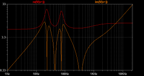
Let's separate the speaker impedance into cartesian reactance and resistance rather than polar magnitude and phase.
Red line is resistance, orange is reactance.
Joe, are you saying the signal through the cartesian resistance is related to SPL, or do you mean only the signal through the wire resistance of the voicecoil?
Red line is resistance, orange is reactance.
Joe, are you saying the signal through the cartesian resistance is related to SPL, or do you mean only the signal through the wire resistance of the voicecoil?
Attachments
For the Powrtron, no. I admit that this cross-coupled phase splitter looks scary but both the C-fb and V-fb paths are inverting. This is an amp that has low distortion from a tight feedback and high output impedance at the same time.Am I standing on my head, or is one of these loop feedbacks positive? Always thought that circuit looked funny.
You just cant rely on imagination when explaining something none trivial if you want your message coming true. Ask a teacher.
//
//
Do you recall the reasoning behind the idea that current drive reduces distortion?The answere has finally been dealt with in some detail within the pages of the book "Current-Driving of Loudspeakers" by Esa Merilainen
I'm sorry but you seem to confuse a thing here.Look at the double-graph, take any frequency and note that any part of the impedance above Re 6 Ohm is caused by some kind of back-EMF, motional, inductive and microphonice - all the deviations of the impedance impugning the current is above the Re value of the driver.
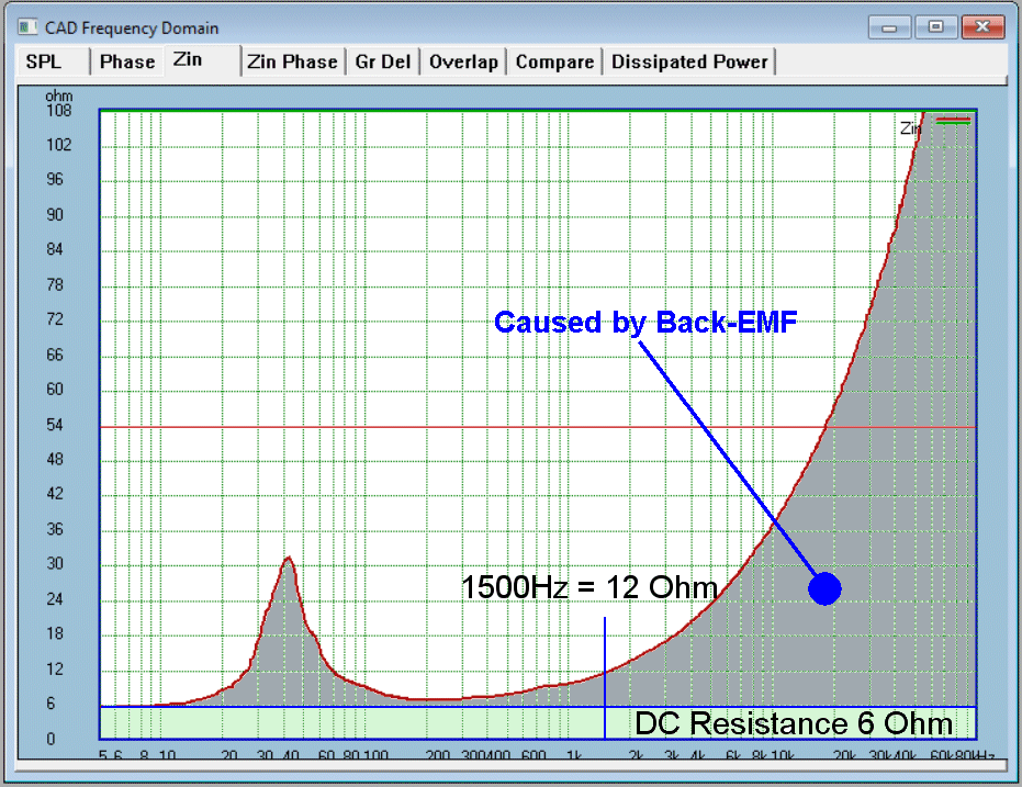
The only deviation from flat in the impedance plot that is caused by back-emf (microphonic voltage) is at/around the peak at the resonance frequency. For constant SPL (= acceleration) velocity falls with 1/f so higher frequencies produce little back-emf. The rise at HF in the plot is from static voice coil inductance. The caption in the graph is plain wrong.
It remains true that high impedance drive gives an SPL increase over low impedance drive at the frequencies where the total impedance, static + dynamic (back-emf-induced), is high because the voltage rises (SPL increase is as proportional to terminal voltage as it is to current). This is sort of trivial, though, it's true for any network not only speakers.
As for listening comparisons, I found them useless when the small signal frequency response isn't carefully EQ'd to be the same (+-0.1dB) when changing drive impedance. With tools like Acourate or LSPcad this is done easily (maybe even REW+RePhase, didn't check that). Then you can find changes in the sonic fine-print quite easily, both by listening and by measuring.
Last edited:
I have the book, I thought it was a trick question.
The EMF induced in the voicecoil contains harmonics from Bl modulation as well as from the magnetizing current of the magnet assembly, as well as skin effect and proximity effect and whatever (the details are fuzzy to me on that part). Well okay, the inductance is induced emf, not back emf.
This voltage subtracts from the input voltage across the voicecoil resistance. At this point the input voltage and back EMF have combined and the resulting voltage swing across the voicecoil resistance includes all the aforementioned harmonics.
As the source impedance increases, the conductance available to the back-EMF to generate current decreases. As this current decreases, so do the associated harmonics.
As far as the diaphragm is concerned, the electrostatic potential between the coil terminals has no direct physical effect. If there was voltage but no current, there would only be insignificant electrostatic forces. The input voltage causes movement only in so far as the conductance of the driver electromechanical system allows it to generate current through the coil.
Last edited:
I do sometimes wonder if we see Poe's law in action here.
That or Einstein's definition of madness....
That or Einstein's definition of madness....
- static impedance does not have an influence anymore --> any changes in the static impedance (Rdc(temp), Le(x), ...) do not change the output.Do you recall the reasoning behind the idea that current drive reduces distortion?
- re-entrant distortion is avoided, that is, the injected force is subject mainly to the nonlinearity of BL(x). The resultant force that the cone sees is the sum of the BL*i force and the suspension spring force. The velocity signal from the voice coil, which is also distorted from a BL(x) curve and other factors, is discarded. The system operates full open-loop with the known effect on the distortion profile.
Current drive does NOT cope with:
- BL(i) flux modulation
- An F(x) component that represents the pull force on the VC into the gap with current of *any* polarity (think of a motor with unenergized magnet to visualize that)
- stick-slip / friction (as this shows up only in the back-emf)
- jump resonance tendency (nonlinear systems with low damping tend to be chaotic under certain conditions)
By BL(i) flux modulation do you mean the coil magnetizing the magnet? IE the coil would have magnetizing current for the magnet which would contain it's material saturation harmonics and nonlinear loss, eddy currents, whatever.
I like Esa Merlainen's analogy of this being as if you put a very lossy, nonlinear inductor in series with the speaker.
EDIT: I guess you can't mean that, if current drive doesn't help.
By stick-slip/friction I guess you are saying there are small particles in the suspension and other materials rubbing and generating noise which can be reduced by the E-braking effect of the back-EMF.
Last edited:
Yes. This error is always there, of course, unless the effect of the current on the magnet strength is eliminated (shorting rings, or even better yet, a secondary static coil in the gap like 18sound's AIC).By BL(i) flux modulation do you mean the coil magnetizing the magnet?
Quite. When we have stick-slip etc the back-emf sensor voltage does not track the needed velocity anymore --> voltage difference across Ze --> correcting current. The higher the feedback (lower Ze) the stronger the correction.By stick-slip/friction I guess you are saying there are small particles in the suspension and other materials rubbing and generating noise which can be reduced by the E-braking effect of the back-EMF.
Last edited:
What you're describing works nicely with classD to save money, and class AB starts not saving much money as power needs increase. Then you're also dependent on quality of DAC/DSP/signal-crossover on top of a source, and extra cables. So it's not like a free zone.
If your source is already digital, you are not adding a DAC quality consideration, it's there either way. It's relatively easy to make a filter in DSP with much better characteristics than an analogue crossover.
And if the electronics is located at the speakers - which is sensible and usually the case in commercial implementations - then you probably net reduce cabling, certainly simplify it - power and optical link only needed...
- Status
- Not open for further replies.
- Home
- Member Areas
- The Lounge
- John Curl's Blowtorch preamplifier part III