John, we know something about the amp from the schematic, but less about the speaker. How about frequency response before and after? Complex impedance vs frequency? Maybe other people are more familiar with that stuff and don't need to ask but I have to look at the models and measurements, as I am not a speaker guy, yet.
Ah 'Doody' . This explains things. Googling 'Doodie' is NSFW.
Then again, I am sure the uk favourite 'muffin the mule' may not be safe to enter into google 😀
Then again, I am sure the uk favourite 'muffin the mule' may not be safe to enter into google 😀
Marsh schematic: modified Leach 1985
Rotated for your viewing convenience.
A 0.15 ohm current sense resistor is in the NFB path through which the speaker ground/neg is routed.
Rotated for your viewing convenience.
A 0.15 ohm current sense resistor is in the NFB path through which the speaker ground/neg is routed.
Attachments
Last edited:
Physics is pretty straight forward but it's easy to get confused by some folks' ambiguous narratives. Everything electrical is current driven, voltage and current go hand in hand. Current is not work. Voltage is not work. Current x voltage is work. 🙂
Only IV (IE)? That is still static. I think someone between posts #3804 - 3864
included time, perhaps you also and other's following along,
as something has to be accomplished over time for it to be "work".
Last edited:
Now this description I believe anybody can wholeheartedly agree with.The key is to understand is that the difference between the two are entirely down to the back-EMF and this test can be done physically and also using a modeling program like SoundEasy. It reveals that only the voltage that appears across the Re of the driver's voice coil is part of the force that creates the final dB-SPL (F = Bl*i) and the two graphs shows the relative difference under current versus voltage drive. The back-EMF part of the impedance is not part of the force, but rather acts like a voltage source, an opposing force to the current. It impedes current and that is what makes it an impedance.
It basically is the equation I've posted earlier: u(t) = Ze*i(t) + BL*v(t). Only the first term contributes to the BL*i(t) force. When it largely dominates the sum then we're in current mode operation, pure force control, whereas when the second term, the "back-emf" largely dominates we have velocity controlled operation where terminal voltage minus "back-emf" is translated via Ze to the driving current. In this case the force is controlled indirectly so as to maintain the velocity that the amp calls for, for that moment in time, it's a control loop effectively.
As mentioned, both schemes, which represent the two extremes within the possible modes of operation with varoius amounts of this local feedback, have their benefits and their drawbacks, and it's upon us to dial in an operating point that works best for us. There are no simple answers.
Last edited:
Static? Usually extremely high V but low I*. Otherwise we'd have people in the southwest dropping dead from cardiac arrest when touching door handles. 😉
*At least low charge, instantaneous current will be very high.
*At least low charge, instantaneous current will be very high.
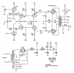
The tube guys also did that, way back. Stan White's POWRTRON for example:Rotated for your viewing convenience.
A 0.15 ohm current sense resistor is in the NFB path through which the speaker ground/neg is routed.
Attachments
The $3000 Pass Labs F7 manual says:
Nelson had to retrospectively design in positive current feedback to give it enough oomph. A method where some care is needed to maintain stability margins and compatibility with different speakers.
Just a warning about the effects of increasing amplifier output impedance too much. I have tried current driving speakers before and had the same result. Polite and initially pleasing but soon dull and unmusical.
In the end, the speaker needs to be controlled.
I thought the amplifier sounded pretty good, but
after a time the consensus was that it was kind of polite, not as musically
involving as some other examples. One area where the amplifier fell
“objectively” short was the output impedance. Most of your “better” amplifiers
have higher damping factors like 20 or 100, and this amplifier was only about 5
or so, typical of a simple Common-Source topology and low negative feedback.
Nelson had to retrospectively design in positive current feedback to give it enough oomph. A method where some care is needed to maintain stability margins and compatibility with different speakers.
Just a warning about the effects of increasing amplifier output impedance too much. I have tried current driving speakers before and had the same result. Polite and initially pleasing but soon dull and unmusical.
In the end, the speaker needs to be controlled.
The tube guys also did that, way back. Stan White's POWRTRON for example:
The very first AES collection of historic speaker papers had some on mixed feedback, nothing is new.
Much of audio is a pretty mature field. Most of the innovation tends to happen when a field is fairly new. Lots of the easy or more obvious stuff gets thought up way in the beginning.
Thank you Miklos for putting up the HCA-855 schematic..
You're welcome.
Accura, that's a good one.
Has a quasi wishbone suspension.
Lot of the complicated stuff gets thought up way at the beginning, too. Oftentimes it requires a lot more technology to realize those concepts. (Just have one look at the crazy awesome stuff NASA, et al, were thinking up in the 50's and 60's that now looks doable)
Anyways, insofar as audibility I'm pretty far into the stuff-after-the-binding-posts matters more than the electrical (or, rather it's not hard to get past audibility on the electronics side), but I can't keep track of this conversation.
Anyways, insofar as audibility I'm pretty far into the stuff-after-the-binding-posts matters more than the electrical (or, rather it's not hard to get past audibility on the electronics side), but I can't keep track of this conversation.
Well, no. That conclusion is a jump too far. They heard a change, but whether that is good for the speaker or not cannot be assumed out of the blue. If you are saying that they thought the speaker sounded better with some series resistance, that's another thing that I can't argue with.
Well, Chris, there was a room full of people that you would have to convince. The output impedance of the amplifier was 18 Ohm and that is in series and yes it was audible (and adding a physical series resistor of the same value would have worked the same), and yes it was better in a mixed way and I did not like everything it did - clearly the alignment was affected and that was a negative, but that was not the only thing that was happening. So both for bad and for good, there was a difference, and if you had been there, you would have heard the exact the same, trust me on that.
The tube guys also did that, way back. Stan White's POWRTRON for example:
Maybe before then. As JC said already, AP used similar circuit concept to reduce their transformer distortion. As this tube circuit does also.
What I find interesting is that my 1985 approach lowers the speakers distortion. I would think everyone would include this in thier amp design for more accurate "sound" from the customers speaker. Any VFA is a candidate for DIY mod. But, no one took it up since at least 1985. Maybe these small hobby mags just dont get enough exposure.
The answere has finally been dealt with in some detail within the pages of the book "Current-Driving of Loudspeakers" by Esa Merilainen
And though it is covered, I didnt see any data/curves related to its loudspeaker driver distortion reduction. So, there is still room for greater detailed explanation.
And, possibly an optimization method. Maybe even a patent in there somewhere.
THx-RNMarsh
Last edited:
Thanks for the clarification. You have said most of that before but never explained what the graph was, all you needed here was "the two graphs shows the relative difference under current versus voltage drive." Can you quantify the voltage at the speaker terminals and the current for those spot-check frequencies you highlighted?
I thought it was obvious.
Can you quantify the voltage at the speaker terminals and the current for those spot-check frequencies you highlighted?
Purely relative, since this is SoundEasy modeling (confirmed by physical experimentation that SoundEasy's internal algorithms are 100% correct), you can assign the values.
So let us say 6V RMS under voltage drive and 1 Amp under current drive. Since the Re DC resistance is an actual 6 Ohm and an actual acoustic measurement of the driver (both acoustic and electrical data imported).
If there was no back-EMF impedance, then the current would be 1 Amp in both cases. So we are now comparing a situation that has an equivalence and the only difference between the two graphs is then entirely caused by the back-EMF impedance.
So we have 1500 Hertz as the example, by which the impedance has doubled. Under current drive, as I explained, this doubling of impedance caused by back-EMF means that the current will drop to half, 500mA.
Since we know that Re is a quantifiable impedance of 6 Ohm, we now can see that the back-EMF also has a quantifiable impedance of 6 Ohm, that makes the total impedance 12 Ohm (notwithstanding that back-EMF also causes a current phase angle).
The back-EMF does not contribute to the dB-SPL output of the driver, it simply opposes (as an impedance) the current of the amplifier. It is also a much less stable impedance that the pure resistance of Re. In fact, any odd deviation in the impedance plot of the driver means that the back-EMF impedance has changed. This can be caused by the many driver imperfections (and when in a box, add box resonances as well). So the back-EMF now changes the current in a dynamic and rather negative/undesirable way. The 500mA that should be stable, is not as stable as it should be.
That 500mA forms a voltage across the Re of 3 Volt. It ought to be stable, except back-EMF makes it less so. The current 500mA x 3V is now 1.5 Watt (without back-EMF it would have been 6 Watt) and of course this is where we see the heat dissipation/energy and what generates dB-SPL (99%+ expended as heat), alas. The back-EMF impedance does not contribute to the dB-SPL and is only an opposing force, because EMF is a voltage source - and it has become a measurable impedance, one that impedes current and hence it becomes an impedance - simple really.
Does that help? There is no voodoo ideas here, they are quite verifiable by anyone. And a reduction from 6W to 1.5W is -6dB, exactly as SoundEasy shows, so take another look below where I have reposted the graphs.
Look at the double-graph, take any frequency and note that any part of the impedance above Re 6 Ohm is caused by some kind of back-EMF, motional, inductive and microphonice - all the deviations of the impedance impugning the current is above the Re value of the driver. It shows a consistent pattern and the maths are the same.
The equation at any frequency is as follows, here using 1500Hz as the example:
1500Hz:
Zload Impedance = 12 Ohm *
Re = 6 Ohm (part 1 of impedance)
Back-EMF = 6 Ohm (part 2 of impedance)
Current drawn from voltage source, 6V/12R = 500mA
12R/Re = 2
Log(2)*20 = 6dB
Now check graph for dB-SPL difference = 6dB
Vre = 6V/2 = 3V **
Watt = 3V x 0.5A = 1.5 Watt
Relative to 6 Watt (full 1 Amp) = 6W/1.5W = 4:1
Log(4)*10 = 6dB
* This impedance is taken as having been derived from 'constant current' method.
** Vre is the voltage that the Re sees as opposed to the voltage that appears across the driver terminals, it is Vre that is used in caluclating dB-SPL.
Pick any frequency and repeat above and you will get the results you see in the double-graph below - without fail.
Attachments

Last edited:
Now this description I believe anybody can wholeheartedly agree with.
It basically is the equation I've posted earlier: u(t) = Ze*i(t) + BL*v(t). Only the first term contributes to the BL*i(t) force. When it largely dominates the sum then we're in current mode operation, pure force control, whereas when the second term, the "back-emf" largely dominates... There are no simple answers.
Nice!
Add: But the maths, this is why modeling programs like SoundEasy gets it right - there is nothing voodoo here! The pros and cons are there for all to discuss - and we should be allowed to do that because we have different priorities.
Last edited:
Purely relative, since this is SoundEasy modeling
Oh I thought those were measurements.
Since we know that Re is a quantifiable impedance of 6 Ohm, we now can see that the back-EMF also has a quantifiable impedance of 6 Ohm, that makes the total impedance 12 Ohm (notwithstanding that back-EMF also causes a current phase angle).
I think you meant to say "At 1500Hz the impedance of the driver is 12 Ohms."
The back-EMF ... is also a much less stable impedance that the pure resistance of Re.
What does "stable" mean to you in this context? Does it mean that the impedance is not always 12 Ohms at 1500Hz?
Or by any of the many electrical, mechanical, and magnetic properties of a perfectly normal speaker without "imperfections".In fact, any odd deviation in the impedance plot of the driver means that the back-EMF impedance has changed. This can be caused by the many driver imperfections (and when in a box, add box resonances as well).
So the back-EMF now changes the current in a dynamic and rather negative/undesirable way. The 500mA that should be stable, is not as stable as it should be.
That is where you lose me. You have shown no evidence that there is anything "stable" or expected or desirable about a purely resistive impedance.
Now what about cases like the one George showed where net impedance is below Re?
What does "stable" mean to you in this context? Does it mean that the impedance is not always 12 Ohms at 1500Hz?
Or by any of the many electrical, mechanical, and magnetic properties of a perfectly normal speaker without "imperfections".
Should I get into grammar? The word stable is relative to what and that is the Re of the driver. The Re is not frequency dependent and you can surely see that the back-EMF impedance is frequency dependent. Now it seems to me that you are asking me to explain the obvious. Even Re is not a totally stable impedance, because it is thermally dependent. But the key here is that the change in the overall impedance, which can be shown to be many things, those variations show up in the back-EMF impedance rather than Re. This in turn causes the amplifier to be bossed around, because being a voltage device, it cannot control the current - hence the current and voltage that appears across the Re (I*V) is changing the force that becomes our dB-SPL of the driver. Effectively, the less stable back-EMF impedance causes the amplifier's current to be modulated and that eventually affects the sound we hear, because the dB-SPL is what we hear.
Again, this is not really that hard to understand, once you have grasped it, it becomes actually very obvious.
Now what about cases like the one George showed where net impedance is below Re?
I missed that, where did George say that and in what context?
My context is the force factor that creates the dB-SPL of the driver. Can you show me any example where the impedance drops below the Re of the driver? If you mean 'net' as the sum of multiple elements between amplifier and driver, that is an entirely different topic - and if you want to go there, fine - but later, OK? Let us get pass this one first.
Last edited:
I'm operating under the assumption that amps are cheap in contrast to chassis/psu, so going multichannel with active crossovers not much more expensive than a bigger 2 channel amp and a fancy passive crossover.
What benefit, if any am I missing by this approach versus the late proposals?
What benefit, if any am I missing by this approach versus the late proposals?
If you really want to have an intelligent communication, please start with an impedance sweep of a driver and specify the operating and testing conditions.
Don’t give Mr. Curl the hard time to co-suffer with you due to the stiff, distorted, engineering brains of the participants.
Here is a KEF B110 in a 7lt sealed, non stuffed box. Really basic test set-up from 15 years back.
George
George, I could do that, but I don't think it would be receptive here. But take a look at that impedance graph, draw a lateral line that represents the DC resistance, the X axis, and look at the impedance that is above that line and ask, what causes it? Also, the impedance below the line, being resistive will have a non-complex impedance, but what about above the line? Below not volatile, resistive stable part of the impedance, above not. I think that is likely as far as I will be allowed to go here. Just watch!
S
I missed that, where did George say that and in what context?
My context is the force factor that creates the dB-SPL of the driver. Can you show me any example where the impedance drops below the Re of the driver? If you mean 'net' as the sum of multiple elements between amplifier and driver, that is an entirely different topic - and if you want to go there, fine - but later, OK? Let us get pass this one first.
Take another look at the actual measurements that George showed you.
- Status
- Not open for further replies.
- Home
- Member Areas
- The Lounge
- John Curl's Blowtorch preamplifier part III