Has the IEEE set the impedance criteria that define a CMA?
Output stage for current-mode feedback amplifiers, theory and applications | SpringerLink
Output stage for current-mode feedback amplifiers, theory and applications | SpringerLink
Last edited:
Has the IEEE set the impedance criteria that define a CMA?
Output stage for current-mode feedback amplifiers, theory and applications | SpringerLink
Thats a strange question. Title is a little misleading. Its a CFA as stated in intro. That is 1992. IEEE did later standardise on the terminoloy. IEEE makes CMA and CFA distinction today.
I have listed here before new/current published book on CMA.
-RNM
Last edited:
Will you, one day, cease your value judgments (always negative and aggressive) without ever demonstrating anything. This is why I have already asked you who you think you are. God, and your opinions as gospel words ?
It seems to me that your criticisms are based more on your personal sympathies towards the author than on an objective and open analysis on the circuits that you criticize.
Reason why I do not have such a high opinion of the value of your points of view that which you seem to grant to yourself.
As I have already been the victim of this same behavior on your part, I allow myself to return the ball to you
Sorry, I'm not playing. The last think I want is an argument with T-E.
Why is it a strange question, forget the link, perhaps the IEEE get confused too. If they don't specify an impedance criteria do you?
Constant-bandwidth current mode operational amplifier - IET Journals & Magazine
Uhuh, and for power amps?
Constant-bandwidth current mode operational amplifier - IET Journals & Magazine
Uhuh, and for power amps?
Last edited:
I dont know of any high end super audio CMA. Do you?
Should I? It appears to me one R.N. Marsh was promoting "CMAs" (whatever that is) as the best audio thing since sliced bread.
IMHO you continue to confuse the amplifier gain type (voltage, current) with the feedback type (voltage, current).
Jam,
Here is a passive 5-pole flat Group Delay LPF for most audio VFA.
I am not concerned about the slight rise at 20KHz.

THx-RNMarsh
Here is a passive 5-pole flat Group Delay LPF for most audio VFA.
I am not concerned about the slight rise at 20KHz.
THx-RNMarsh
Last edited:
Should I? It appears to me one R.N. Marsh was promoting "CMAs" (whatever that is) as the best audio thing since sliced bread.
IMHO you continue to confuse the amplifier gain type (voltage, current) with the feedback type (voltage, current).
No you are confused about that. I dont confuse them.
I was promoting higher SR amp toplogies. The old rule of thumb of 0.5-1v/us/v did not fit the reality of todays HF situation.
That created a whole DIY forum was devoted to high SR designs and I took away Damir's design. It isnt a CMA either.
-Richard
Last edited:
No you are confused about that. I dont confuse them.
I was promoting higher SR amp toplogies. The old rule of thumb of 0.5-1v/us/v did not fit the reality of todays HF situation.
Ok, I will admit confusion for a second 😀. Now, after pleading confusion, could you please write one short paragraph with the clear definition of a "CMA", to your understanding? That would definitely clear the muddy waters and could constitute a basis for further discussions.
Again. I can mentally assume that the rule of thumb of 1V/uS per each output peak volt is not good enough, could you please show an audio signal that requires more than that? That is, and audio signal that slews faster than the rule of thumb, so the amplifier would be the limiting factor.
Jam,
Here is a passive 5-pole flat Group Delay LPF for most audio VFA.
I am not concerned about the slight rise at 20KHz.
View attachment 802502
Looks like a Bessel filter. I must have missed something, what is the relevance?
OMG Where have you been lately?
NO. I am not going back to explain it to you.
This is beginning to bore me.
THx-RNMarsh
NO. I am not going back to explain it to you.
This is beginning to bore me.
THx-RNMarsh
That's true, but it hasn't happened so far, and how long has this been going on?Ok, I will admit confusion for a second 😀. Now, after pleading confusion, could you please write one short paragraph with the clear definition of a "CMA", to your understanding? That would definitely clear the muddy waters and could constitute a basis for further discussions.
OMG Where have you been lately?
NO. I am not going back to explain it to you.
This is beginning to bore me.
That's fine, so no definition you can write down. I'm happy you are bored, BTW.
That's true, but it hasn't happened so far, and how long has this been going on?
Perseverare diabolicum

hahha. yeah. Its boring to go back for each person who comes to the party late.
Look -- there is a lot of HF above 20KHz. A lot of digital artifacts which is supposed to be all filtered out but isnt all gone. fairly high levels which get amplified. I showed the spectrum analyzer of that HF junk. If an amplifier isnt linear up there, IM can fall back into audio range.
Many audio VFA may not be as linear up in HF area as CFA. It is harder, at least. So, LPF is applied to VFA input to keep HF junk from creating audible IM. Or even potentially audible.
If you need something really dumbed down.... constand BW vs gain = CMA.
THx-RNMarsh
Last edited:
Well, I agree about some of that. But it is only to learn the difference and what a CMA is and does. I dont know of any high end super audio CMA. Do you?
-Richard
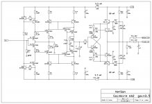
Richard, schematic you showed use current conveyor, is that definition for CMA?
Have you heard of SATRI circuit used in Bakoon amps? AMP-41 - Bakoon International Corp.
I use in my GainWire mk2 and mk3 current conveyors.
attached preamp with SATRI circuit and GainWire mk2 with volume control after IPS (current conveyor), no GNFB used.
Damir
Attachments
Last edited:
hahha. yeah. Its boring to go back for each person who comes to the party late.
Look -- there is a lot of HF above 20KHz. A lot of digital artifacts which is supposed to be all filtered out but isnt all gone. fairly high levels which get amplified. I showed the spectrum analyzer of that HF junk. If an amplifier isnt linear up there, IM can fall back into audio range.
Many audio VFA may not be as linear up in HF area as CFA. It is harder, at least. So, LPF is applied to VFA input to keep HF junk from creating audible IM. Or even potentially audible.
If you need something really dumbed down.... constand BW vs gain = CMA.
THx-RNMarsh
I asked about that Bessel filter, what is the relevance in the current context?
Now that you repeated the same (IMHO wrong) explanation about why we would need high slew rate, let me come up with a numeric example:
In order to avoid ANY large signal slewing distortions, EE101 tells us that the amplifier has to have a slew rate larger than SR=2*PI*Vp where Vp is the amplifier output peak voltage.
Let's take a rather extreme example of an amplifier delivering a continuous 400W/4ohm load (which I hope you would agree it is more than enough for any imaginable home use) and a bandwidth of 200KHz (which is 10x the maximum audible frequency range). To avoid the large signal slewing distortions, this amplifier needs a SR of 2*3.14*56*200000~70V/uS. Note that the rule of thumb delivers 56V/uS. I don't see any reason why a lareger slew rate is required, your "HF over 20KHz" argument is simply false, since it is supposed to be removed by the input filter that any competently amplifier employs.
This input filter not only removes the HF junk, but it is also avoiding any entering into slewing limitations; that's because the input signal slewing will be limited to the input signal amplitude divided by the rise time that is 0.35/bandwidth[GHz]. So any slew rate provisions in the amplifier are in fact completely useless, since the slewing limitation will never be reached.
Really Richard, you could use a light reading (like the Bob Cordell book) where these issues are competently addressed.
Richard, schematic you showed use current conveyor, is that definition for CMA?
I have already mentioned in this thread, current conveyors are occasionaly associated with "CMA", a current mirror being one of the simplest current conveyors example.
I don't think there is an universally accepted "CMA" definition outside this occasional association; which largely overlaps with the "current amplifier" concept. A "current amplifier" can take both current feedback or voltage feedback and there is nothing conceptually that says a "current amplifier" (or "CMA", thereof) has some intrinsic high slew rate provisions.
The "current on demand" (leading to high slew rates) is a property that can be implemented in both VFA or CFA (which in turn can be applied to both a "CMA" and a "VMA" (by association, a "VMA" would be a "voltage amplifier"), and I have shown examples of both, if you recall; "current on demand" is mostly known by it's implementation in the CFA diamond buffer topology, though.
Last edited:
Richard,
As much as it pains me, I have to agree with syn08 on this one. (must be getting soft in the head)......... 😀😀
From what I gather to get a working CMA (for audio applications) you need a 1)buffer 2)gain amplifier 3)CMA (current conveyor) and 4)output stage (to handle complex loads).
The scary part is the complexity required to maintain bandwidth and distortion numbers which are academic at best and could hurt the sonic performance of the unit. So now we need four separate blocks to do what you can do in one or two, with the added complexity of dealing with stability issues of getting all these blocks to work together. Sounds like a solution in hunt of a problem.
Krell used this topology (or should I say ideology) in their Cast system and it was universally panned. It sounded flat and lifeless though it claimed low distortion and wide bandwidth.
Maybe you could publish a working circuit to prove me wrong and I will stand to be corrected.🙂
Jam
Last edited:
I asked about that Bessel filter, what is the relevance in the current context?
Now that you repeated the same (IMHO wrong) explanation about why we would need high slew rate, let me come up with a numeric example:
..
WOW. You really dont get it, Waly. It is the linearity above 20Khz which is not always steller in VFA. It may have a BW > 20KHz but that is no guarantee it is low distortion over the entire BW of the amplifier. usually, the neg FB falls off and distortion rises.
I said higher SR amps also seem to sound better and that maybe the distortion is lower at HF.
The filter on a VFA would be preferred to limit the signal BW IF the amp cannot linearly amplify HF and cause IM <20Khz.
You are boring me Waly.
-Richard
WOW. You really dont get it, Waly. It is the linearity above 20Khz which is not always steller in VFA. It may have a BW > 20KHz but that is no guarantee it is low distortion over the entire BW of the amplifier. usually, the neg FB falls off and distortion rises.
I said higher SR amps also seem to sound better and that maybe the distortion is lower at HF.
The filter on a VFA would be preferred to limit the signal BW IF the amp cannot linearly amplify HF and cause IM <20Khz.
You are boring me Waly.
Thanks Richard, you just proved you are unable to read more than 2 lines in a post and get through some elementary calculation. Nothing you are saying above holds any water, and to add insult to injury you are saying that an input filter is required only for a VFA. For the very wrong reason (in fact, it is intended to avoid EMI ingress, same for CFA, "CMA", VFA).
"R.N Marsh finds me boring", this catch phrase should go straight on Waly's resume (if he's still reading here).
- Status
- Not open for further replies.
- Home
- Member Areas
- The Lounge
- John Curl's Blowtorch preamplifier part III