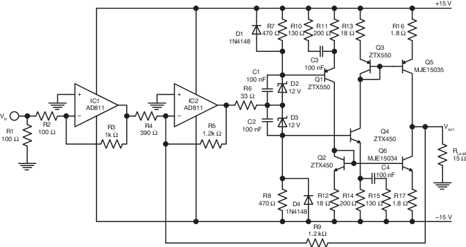
Here is a nice Current-Mode Amplifier (CMA) example I am going to try and measure and listen.
comments? Needs some adjustment to schematic;
View attachment 802429
THx-RNMarsh
I was going to say looks like a nice oscillator circuit but Jam beat me to it.
Have you actually had much experience with AD811? It can be a tricky beast.
T
No Not with 811. but, I do have RF/micro-wave back ground and so could handle most wide bandwidth layouts. But, if there is another similar IC packaged device you would recommend as a better substitute I would try it. I think it might be a good example of making a CMA using a couple CFA.
THx-RNMarsh
THx-RNMarsh
Last edited:
I have Richard, a variation of the circuit I posted.
Issues you usually have to add a buffer (which increases the complexity) and usually an additional gain and then add compensation to get the whole mess to work in harmony, no elegance here. I still don't see the need for DC to light bandwidth, could you explain that one to me.
Problem is, it might measure good but they sound flat and lifeless once you have it working (probably due to all that complexity).
Maybe Richard you should post a working circuit, that you think qualifies, that we could build and test.😉
Jam
Jam,
I have explained why you need low distortion past 20Khz.
Or a LP filtered input. I use a 5-pole passive flat GD filter on the input.
No it doesnt need to be 100MHz, of course.
But, if you make a CMA it is inherently going to be wide band width. How wide depends on the Ft of the devices you choose.
I also described a CMA amp from decades ago... discrete transistors. Simple circuit. Proof of concept thing.
-Richard
Your circuit doesnt follow mine nor JC's rule to be as simple as needed only.
Cant comment on a person's likes or dislikes.
Last edited:
Here is a nice Current-Mode Amplifier (CMA) example I am going to try and measure and listen.
comments? Needs some adjustment to schematic;
THx-RNMarsh
Q1 Q4 bases AC shorted etc. sure doesn't instill any hope for good PSRR figures, add to that even poorer CMRR and PSRR from the AD811, ok that one could easily be swapped for a more hifi emphasized, but still... Richard we sure need to have a better circuit for audio before it becomes interesting studying CMA, any suggestion?
Q1 Q4 bases AC shorted etc. sure doesn't instill any hope for good PSRR figures, add to that even poorer CMRR and PSRR from the AD811, ok that one could easily be swapped for a more hifi emphasized, but still... Richard we sure need to have a better circuit for audio before it becomes interesting studying CMA, any suggestion?
Hmmm OK. See my comments above, first. Yes, a number of things would be needed to fix it up for high quality audio use. R1 being 100 Ohms also wont work. .........
I will think of something else. BUT the point is to know the difference between CFA and CMA characteristics. Because there has been a lot of confusion about what is what or both are same thing etc.
So, one should look at the circuit from that point of view.
THx-Richard
Last edited:
Lesser PSRR in low frequencies is obvious, comparing CFAs to VFAs. But it can be addressed with some care PSU side.Q1 Q4 bases AC shorted etc. sure doesn't instill any hope for good PSRR figures, add to that even poorer CMRR and PSRR from the AD811, ok that one could easily be swapped for a more hifi emphasized, but still... Richard we sure need to have a better circuit for audio before it becomes interesting studying CMA, any suggestion?
Sorry, but I don't see your reason for laughing.Ha ha, I wonder if you had not understood my schematic ? I use this servo AND this optional error correction you suggest (that you can switch in or out). Not at all the same purpose.
The servo is a servo, as it has no effect on the audio bandwidth, but only on DC and ultra low frequencies.
Just lke any other. The difference is the audio singnal has been removed by the comparator in order to add ecciciency and minimize any sonic impact of the servo.
See the original:
Pizzicato, a 200W low distortion CFA amplifier
I should have included the original image of your "servo" that is even called servo.gif.
The text that you added to this image was:
Here, the unusual* servo I use in this project.(See attachment)
The original audio signal is canceled in the comparator, before to be filtered and the remaining DC error applied.
It seems you have forgotten all this.
But as mentioned, it is not a servo in the sense that it removes DC from the output, it is just a BW crippled AEF (Active Error Correction), crippled because of the LPF you inserted.
I have included the gain resistors in the AEF so you can compare both for better understanding.
As a matter of fact, the error cancellation ratio of Ve1 is roughly equal to A2.
Hans


Last edited:
Current Mode vs Voltage Mode Nelson's posts should hopefully helpBUT the point is to know the difference between CFA and CMA characteristics. Because there has been a lot of confusion about what is what or both are same thing etc.
Richard,
I tracked down the article of the schematic you posted and as I suspected it is a video/RF amplifier and I am trying to understand its use in our application(audio). The author says that to maintain stability you have to limit the gain and I suspect the amp is only stable into a specific load and not a real world speaker.
Jam
Good find, and to publish like this without quoting a source would get you fired from any reputable research position. Richard, why did Jam have to do this for you, if I may ask?.
Current Mode vs Voltage Mode Nelson's posts should hopefully help
IMO You should be using the terminology of IEEE for this type circuit and not N.Pass or any one here.
I know some might think this DIY forum is a reputable research place, but i dont.
-Richard
Last edited:
As you've said it depends on the impedances of the circuits used, I don't see the mystery, unless it's where to draw the line?
As you've said it depends on the impedances of the circuits used, I don't see the mystery, unless it's where to draw the line?
That is the key. As I explained earlier.
In order for a small limited dissipation package like IC to make use of high currents to charge stray C etal... would not work well esp. for low Z loads UNLESS there was a way to have current on demand -- thus, the diamond buffer. add-on.
But, for audio you dont need a diamond buffer and can just run high bias class A with low impedances. ;-) So, it is much like a CFA but with low Z. The high bias currents allow fast charge of C's = the high slew rates and wide BW. BUT, there is a little more to get the constant BW with gain effect. But, not too much. It is a special class or Mode of operation.
There is very little in the way of voltage changes. Great for low voltage PS use. Low voltage circuitry depends on currents... not enough voltage margins at low PS volts - VFA.... Rather it is all with current changes within circuit, might be another way to put it. Thus, the name Current-Mode Amplifier.
THx-RNMarsh
Last edited:
No Not with 811. but, I do have RF/micro-wave back ground and so could handle most wide bandwidth layouts. But, if there is another similar IC packaged device you would recommend as a better substitute I would try it. I think it might be a good example of making a CMA using a couple CFA.
THx-RNMarsh
Probably AD844. You get access to the internal 'TZ' node so it allows more
flexibility with designs. You can even run it as an open loop I-V by inserting
a 'load' resistor from 'TZ' to ground and driving current into - IP = current
conveyor.
Many people use it as such but personally I prefer to make discrete current
conveyor I-V's, much better to optimize. With true current OP DAC's
I can get around -120dB (or maybe even better) distortion.
Honestly Richard, I think you have a bit of a fixation on current FB circuits. To
me they are just one tool in the tool box. Sometimes they are the right tool
and sometimes not.
T
Probably AD844. You get access to the internal 'TZ' node so it allows more
flexibility with designs. You can even run it as an open loop I-V by inserting
a 'load' resistor from 'TZ' to ground and driving current into - IP = current
conveyor.
Honestly Richard, I think you have a bit of a fixation on current FB circuits. To
me they are just one tool in the tool box. Sometimes they are the right tool
and sometimes not.
T
Thank you for the suggestion. I only have this fixation here because so many people, including Scott, keep saying a CMA is a CFA etc. If it is clear to all, then we can move on.
THx-Richard
And we use bipolar electrolytics for coupling 😉, which is what I've used in my Doug Self preamp 🙂
I only have this fixation here because so many people, including Scott, keep saying a CMA is a CFA etc. If it is clear to all, then we can move on.
No it is not. Please keep glossing about “CMA”. BTW, the circuit you missed to quote the source for is an abomination for any audio purposes, starting with performance and ending with the load dependent gain. Don’t forget to post some measurements results when you will finish experimenting with, then some listening impressions from a collective sighted session.
I was not laughing at you, but the fact you proposed an idea that was part of the original design. Some kind of complicity, in my mind.Sorry, but I don't see your reason for laughing.
But I'm sorry, the DC servo i use IS a DC servo, by its definition.
A system that reduce the DC offset of an amp auto compensating it automatically.
I don't understand your controversy. In both cases (traditional VS this one) the audio signal is eliminated as much as possible, then the DC error is applied to the main amp input as a negative feedback.
Here, the only difference is the original audio signal is canceled as much as possible by the comparator, before the low pass filter. With all the obvious benefits that we can expect. One of them being less influence in the audio bandwidth of the OPAs as only the LTP of the comparator (input stage) has to deal with the original audio signal.
May-be Mr Marsh will explain-it in a better English than myself, as he is well known for its contribution in DC servos, and had understood immediately my idea. Original ? I think so, because I never seen this idea applied before to a DC servo.
Now, may-be you wonder why error correction was not enough to compensate the offset ? It is very easy to, explain. The phase turns at HF limit the amount of correction you can add. At low frequency you can apply a lot more. All the stability margins, response curve at low frequencies and speed of the servo had been seriously studied and optimized.
It seems very strange to me that, every time somebody propose a solution that bring improvements and is a little out of the box, somebody begin to argue against-it, not trying to understand or test-it.
Last edited:
No it is not. Please keep glossing about “CMA”. BTW, the circuit you missed to quote the source for is an abomination for any audio purposes, starting with performance and ending with the load dependent gain. Don’t forget to post some measurements results when you will finish experimenting with, then some listening impressions from a collective sighted session.
Well, I agree about some of that. But it is only to learn the difference and what a CMA is and does. I dont know of any high end super audio CMA. Do you?
-Richard
Last edited:
Will you, one day, cease your value judgments (always negative and aggressive) without ever demonstrating anything. This is why I have already asked you who you think you are. God, and your opinions as gospel words ?No it is not. Please keep glossing about “CMA”. BTW, the circuit you missed to quote the source for is an abomination for any audio purposes, starting with performance and ending with the load dependent gain. Don’t forget to post some measurements results when you will finish experimenting with, then some listening impressions from a collective sighted session.
It seems to me that your criticisms are based more on your personal sympathies towards the author than on an objective and open analysis on the circuits that you criticize.
Reason why I do not have such a high opinion of the value of your points of view that which you seem to grant to yourself.
As I have already been the victim of this same behavior on your part, I allow myself to return the ball to you
Last edited:
- Status
- Not open for further replies.
- Home
- Member Areas
- The Lounge
- John Curl's Blowtorch preamplifier part III