The UN 🙂 YouTube
I can't believe I once passed up the chance to see PJ Harvey in PDX, opening for U2 or some other shite. I'm sure that she would have picked this old geezer out of the nosebleed section and fallen in love with me, and we would have lived happily etc. That's yet another version of reality.
Great riff on the old Blue Cheer (and even earlier) classic. LUV me some Polly.
All good fortune,
Chris
Last edited:
And the most politically correct country is ...... 🙂
That's a really disturbing question at heart. How much is a good thing? In America right now these sorts of questions are being asked everywhere. Painful and difficult, but necessary, as you imply.
Much thanks, as always,
Chris
Last edited:
In Europa, many people, many, are aware of it. And terrorized, believe-me.We live in a time of wars and rumours of wars. My own country is approaching a second Civil War but nobody dares to talk about it.
And, unless to be totally blind, it is not only your "own country" in concern, but the all world. Brexit, as an example.
A French great 'intellectual' (André Malraux) said, in the middle of the last century: "The twentieth century will be religious or will not be". I'm afraid he made a typo:
The twentieth century will be religious then will not be.
History has taught us that one is often the logical consequence of the other.
PS: Touched, PMA. You are even more brutal when you are deep. ;-) I will start reading you between the lines ;-).
Last edited:
I really don't want to get into this, but I suspect it is necessary.
The biggest potential compromise in the output are the output connectors. You should test them for steel content. Get a magnet, and if the magnet is extremely attracted to the connector, it should be replaced if possible. A potential improvement also 'might' be to solder directly the output cables to the output connector. Usually this is almost impossible without a huge soldering iron or a flame torch. Is it worth it?
Thanks JC,
I understand your position of not wanting to open a can of worms.
And I thank you for what input you are giving.....like I said I’ll leave the zobel alone and will probably get some high quality output connectors.
Hopefully they are just tightened onto the zobel PCB and come apart easily, after disassembled it would be easier to solder it back.....I have a heavy duty gun that would probably work.
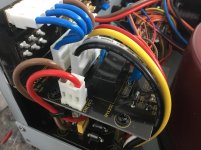
If you could maybe comment on those ferrites in question on the mains input(the two on the bottom board near the yellow cap)
that would cover what’s been questioned.
It is about the sound after all?
Thanks again,
Bob
Attachments
Probably not. Thankfully Bob listens to what you say. For what it's worth I might do something about the connectors onto the board.
I would think soldering as many of those connectors as possible would be beneficial.....seems as though it was a ease of assembly/repair thing, definately not a optimal quality thing. In fact the parts and PCBs seem very high quality but assembly does not.
In fact the parts and PCBs seem very high quality but assembly does not.
The assembly is cost-effective first and can be done much better by DIY.
I exhibited a headphone amp yesterday at the Burning Amp Festival in San Francisco, using 1971 era semiconductors. Specifically the LH0033, which was/is a Linear Hybrid device. Today we'd probably call it a multi chip module. It's a ceramic substrate upon which discrete JFETs, BJTs, and resistors are die-attached and wire-bonded to a metallization pattern. Exactly like a 1 layer SMD printed circuit board, except (a) bare die instead of packaged parts; (b) wire bonded instead of reflow oven soldered, and (c) ceramic substrate instead of FR4.
I've owned a fistful of LH0033s for at least 25 years, and finally decided it's time to Build Something out of them. To my delight I discovered there are still a few places online who sell NOS LH0033s (!), and for less money than NOS vacuum tubes. Just as a verification test, to find out whether the quotes were real or vaporware, I ordered two LH0033s last month from Quest, and paid $25 apiece. They arrived six days after I placed the order.
My amp used LH0033's as the final output stage, driving the headphone load. They're particularly good at this, since their DC bias current is 60 milliamps {see datasheet}. In effect they're a wideband class-AB buffer, with the transition from Class-A to Class-B happening around 100 or 120 mA of output current. Just what the doctor ordered.
I attached some fairly large heatsinks to the 12 pin, TO-99 round cans, using Phase Change thermal pads from Laird (datasheet) plus mechanical tie-down. The heatsinks run cool to the touch.
Attendees listened to it either using their own headphones or the Audio Technica's that I brought. Response seemed to be quite favorable.
I may open a new thread about it sometime this month; the HPA goes by the name "Azul".
_
Attachments
Last edited:
Yes you have it, the overall design is excellent.....JC's schematics and Taiwan layout parts and production techniques.I would think soldering as many of those connectors as possible would be beneficial.....seems as though it was a ease of assembly/repair thing, definately not a optimal quality thing. In fact the parts and PCBs seem very high quality but assembly does not.
Yes, the output terminal arrangement is ideal from production/assembly point of view but could be better sonically as I have been saying.
The RC network values are 0.047uF Polyester cap and 5.6R Metal Oxide Film resistor I think.
There is much room to experiment with types of both C and R....the resistor type is chosen because it is rugged and fail safe....no smoke/flames/fire and the cap because it's pretty cheap and on measurements does the job (unless JC chose it by auditioning).
I say the output terminal pcb is 'voicing' the amp to some extent, ie all the parts involved (connectors and RC and pcb material) set a tone, and in this case I reckon will be dirtying the tone.
I have never found polyester caps to sound good (see the link above), and the MOX resistors are noted for being noisy and the tempco is not very good, and I am suspicious of their sound, IIRC they cause an odd dull sound.
So you have opportunity to do some tuning by removing the pcb and soldering new RC networks and the speaker wires directly into the back of the banana posts.
I am finding that Metal Film resistors across my amp and speaker terminals sounds nicely clear, Carbon Film sounds 'musical' but dirty and veiled.
Two standard 2R7 0.6W MF resistors in series (solder one into each post in addition to speaker wire) with a 0.047uF/47nF polypropylene cap bridging the resistors would work and I expect lift the sound nicely.
This arrangement costs only a few dollars, is easily available and allows easy AB experimenting with cap or resistor types but the MF/PP network will be close to optimal IME and is what I would try in this case.
Dan.
Ferites and speaker output cables are next subjects.
Last edited:
Cool, thanks Dan,
I know for fact that sound can be shaped with different materials/manufacturer of the same values, as evidenced in my xo experiences.
I’m probably going to try just better outputs soldered straight first (with the stock zobel) and go from there. I like going slowly,one change at a time or you never really know where your at!
Cardas makes some good outputs.....I’m thinking gold plated copper would work best.
And btw.....I am archiving everyone’s pertinent suggestions, so your time/effort will not go to the wayside!
Last edited:
Yes, expect it..Cool, thanks Dan,
I know for fact that sound can be shaped with different materials/manufacturer of the same values, as evidenced in my xo experiences.
Ok, first off chop the connectors and solder the speaker wires directly to the banana posts.I’m probably going to try just better outputs soldered straight first (with the stock zobel) and go from there. I like going slowly, one change at a time or you never really know where your at!
Huh, if you want to spend Cardas cash but I reckon the originals are ok, probably less influence than the connectors pcb and Rc network.Cardas makes some good outputs.....I’m thinking gold plated copper would work best.
Dan.
I’m sure there’s probably a cheaper alternative if I dig a little......just think straight copper would be less of a bottleneck?
- Status
- Not open for further replies.
- Home
- Member Areas
- The Lounge
- John Curl's Blowtorch preamplifier part III