I did include the .asc of the Pease Mylar cap linear DA model in http://www.diyaudio.com/forums/the-...owtorch-preamplifier-ii-9966.html#post5335040
anyway, here's the step response diff (x1000)
~72 dB down for the 20 ms pulse ~ 1/2 a 25 Hz square wave
anyway, here's the step response diff (x1000)
~72 dB down for the 20 ms pulse ~ 1/2 a 25 Hz square wave
Attachments
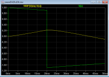
Looks like the square wave is not symmetrical about zero (non-50% duty?) so we see a varying DC on the cap. As theory predicts for an ideal cap. ;-)
Jan
Jan
I did include the .asc of the Pease Mylar cap linear DA model in http://www.diyaudio.com/forums/the-...owtorch-preamplifier-ii-9966.html#post5335040
anyway, here's the step response diff (x1000)
~72 dB down for the 20 ms pulse ~ 1/2 a 25 Hz square wave
That looks reasonable to me, although the pulse droop is different than in John's photos. It shows that the caps differ for a time around the transients then settle to the same baseline. It's what would be expected from a multi-pole ladder filter compared to a single pole RC filter. It would be helpful to see a less horizontally expanded view too, with a few cycles shown so we have a better feel for the bigger picture.
What I don't get about the scope images in John's article are the short sort-of-hysteric differences around pulse switching transients. It looks like either some nonlinear distortion in a cap or some problem with the test apparatus. Unfortunately there are no time-scale expanded images of the transients, and no explanation by the authors of what they think the images show, especially in that region.
Last edited:
Servos have their specific issues as well. Their promoters should be that fair and explain it.
That is true and they can cause issues themselves if not implemented in best way.
We should discuss it , I agree.
THx-RNMarsh
Is it really a problem? C0G ceramic measure almost the same and are a lot more modern assembly process friendly. PS doesn't like the heat, that's for sure.
yes, that is also true. many good caps to choose from today. Emphasis is on Today.
I think we keep forgetting that the original goal of mine was to eliminate electrolytic --bipolar- coupling caps common to the era. Which lead directly to topologies with zero dc on the output and to dc servo concepts.
The differences in films with low DA is very small. You would be hard pressed to tell the difference in a Dblt. However, the tiny differences seem to matter to ultra high-end people.
THx-RNMarsh
Last edited:
Emphasis on today should also mean that the "back in 1979..." type arguments should die immediately. As has been measured, a large, quality bipolar electrolytic in line level/feedback leg is so far down as to essentially render the point moot.
I realize it doesn't make for a sexy sell or anything, but bigger fish to fry?
I realize it doesn't make for a sexy sell or anything, but bigger fish to fry?
The map is clearly incorrect. In Mel Brook's "Spaceballs" we could
clearly see that the princess drove a Mercedes in space.
Gerhard
Your right, but I thought you where going say, "the US is not green" 🙂
Looks like the square wave is not symmetrical about zero (non-50% duty?) so we see a varying DC on the cap. As theory predicts for an ideal cap. ;-)
Jan
Geeeeez. I go away for 30+ years and come back to find the same things talked about.
but, you bring up a point I can go deeper into.... I wrote an article in Audio magazine about it.... common-mode signals.
In short form.... I said complex music signals have a varying average which is a signal itself. A common-mode signal.
And, That is the reason to have high CMR in your High-End amplifier designs. Also, said at that time, dynamic power supply variations create a common-mode signal to the amp. I told you that cascoding helps reduce the effects of CM signal from the PS. In another article, I showed the topology for a push-pull shunt regulator to keep the V+ and V- the same under dynamic load conditions. You don't need super duper regulated PS voltages - just keep the 2 voltages always the same under dynamic conditions.... reduced CM signal affecting the amplifier.
It is quit likely (conjecture) that any audible results from cascoding in a PA with unregulated PS is due to this and not HF lowered distortion.
Go deeper please.....
The best thing for audio i have seen in the past decades is further CFA development and more linear topologies. VFA and CFA and CFA+B designs.
The other is greater acceptance for shunt push-pull regulators for High-End designs.
Meanwhile, i went into acoustics and speaker designs. And, lots of T&M. Built many systems... active and passive. I learned the same things about those systems as JBL researchers and they put it all together with incredible drivers. Their M2.
THx-RNMarsh
Last edited:
I said complex music signals have a varying average which is a signal itself. A common-mode signal.
For a single ended signal there is always a common mode, it has nothing to do with "complexity". I can see the asymmetric signals coming again.
You guys seem to miss the 'forest' for the 'trees'. Typical low cost, medium-high volumetric efficiency caps have multiple problems compared to the highest quality film caps like Polystyrene, Polypropylene, or Teflon.
DA is just part of the problem, but non-linear distortion, tempco, microphonics, and hysteresis are also factors, depending on the cap type.
Asymmetric signals are the norm in audio, not pure sine waves like we like to use for testing. DA shows itself in a real way with asymmetric signals, as a non-nullable error and that is why the test signal that Walt and I used is asymmetrical.
Is this differential comparison test perfect? NO. In fact, Richard Marsh declined to participate in the paper, because he thought the test was not ideal in depicting DA accurately. However, I saw that the test was relatively easy to implement (thanks to Scott's AD524 that is very good in this application) and that it invariably showed that 'something was wrong' with how most cheap caps handled this sort of test signal, compared to better caps, yet could look pretty good with just sine wave testing. It can be seen that the actual signal path is modified in a different way than the best caps due to DA, non-linear distortion, etc and this is what is important to note. Now, of course, ALL caps will change the waveform, if the RC time constant is set close to the edge of the input pulse, square wave, or whatever complex waveform is used, but since the 'good' caps measure similar to each other, no matter who made them, or even what material (Teflon, Polystyrene, or Polypropylene) then the 'bad' caps are made of material that has high DA and should be avoided. I suspect that even COG ceramic caps have fairly hi DA, so they might be avoided as well, especially in higher values.
This test set-up is not perfect, but we did compensate for any RC time constant differences and even some nominal internal resistivity differences that some caps have. The idea is to simply minimize the error signal by adjusting it out, if possible. The test waveform, determined experimentally by me, through testing hundreds of caps, brings out the worst case that I could, while still staying within the audio range, and it was deliberately bandwidth limited in order to minimize any TIM or slew rate aberrations, and even the effective difference between any residual inductance in the caps. Still the test is not perfect, and can be nit-picked to death, but then you have 'missed the forest for the trees'. '-)
Last edited:
JC, RNMarsh, let me ask you questions concerning servos in your amps. Imagine there is a sudden DC jump at the input of your power amplifier (for example a failure in the preamp before the power amp), so suddenly there is a +DC at the input. Assume that the DC amplitude might be +3V, +5V, +15V, depending on preamp failure. Two questions:
1) will your DC servo be able to handle such DC amp input without saturation (and without latch up), and if yes, how long it takes to decrease amp Vout to some hundreds of mV, and where is the input threshold that would not saturate the servo.
2) in case that the servo is in saturation, which is inevitable above some DC threshold level, is there always a DC protection circuit that would save the speakers.
Asymmetric signals are the norm in audio, not pure sine waves like we like to use for testing. DA shows itself in a real way with asymmetric signals, as a non-nullable error and that is why the test signal that Walt and I used is asymmetrical.
See, told you so.
The map is clearly incorrect. In Mel Brook's "Spaceballs" we could
clearly see that the princess drove a Mercedes in space.
Gerhard
NASA has left a few Lunar Rovers parked on the Moon since the early 70's🙂
Did the Russians leave anything mobile on the moon? Or the Chinese on Mars? They did go there, didn't they?
Edit: Lunokhod 1
Jan
Edit: Lunokhod 1
Jan
Last edited:
For a single ended signal there is always a common mode, it has nothing to do with "complexity". I can see the asymmetric signals coming again.
complexity OR music...... complex compared to sine wave where sine wave average is zero.
-RM
JC, RNMarsh, let me ask you questions concerning servos in your amps. Imagine there is a sudden DC jump at the input of your power amplifier (for example a failure in the preamp before the power amp), so suddenly there is a +DC at the input. Assume that the DC amplitude might be +3V, +5V, +15V, depending on preamp failure. Two questions:
1) will your DC servo be able to handle such DC amp input without saturation (and without latch up), and if yes, how long it takes to decrease amp Vout to some hundreds of mV, and where is the input threshold that would not saturate the servo.
2) in case that the servo is in saturation, which is inevitable above some DC threshold level, is there always a DC protection circuit that would save the speakers.
There are several ways to place a servo within circuit to control dc on output.
The goal is not to correct (imo) a fixed dc offset. A well balanced push-pull should be matched well enough to have very little dc offset and could be trimmed from there to zero. The dc servo, as I would apply it is only to correct for drift in output due to heating, thermal unbal., bias changes etc and thus would have a long time constant.
A long time constant would not be useful for input overload protection.
So, yes, there is always a DC protection circuit used to save the speakers.
THx-RNMarsh
Last edited:
complexity OR music...... complex compared to sine wave where sine wave average is zero.
I wish the AES was rigidly PhD level peer reviewed to eliminate this lightweight stuff.
I wish the AES was rigidly PhD level peer reviewed to eliminate this lightweight stuff.
Would that exclude you as a reviewer?
- Status
- Not open for further replies.
- Home
- Member Areas
- The Lounge
- John Curl's Blowtorch preamplifier part II