Mark: Your chart shows 'colouration' and 'clipping' under distortion. Both of these is a very gross level effect and the other usually only shows at very high distortion levels. In his text linked Olive says 'Distortion sub-attributes include the presence of noise, hum, audible clipping and distortions specific to the audio device(s) under test' . No explicit mention of 'THD'. In the grand scheme of things is does appear that the distortion Richard worries so much about is a very low priority to him?
But two thumbs up for him trying to drag people from arm waving and veils into something more controllable and repeatable.
But two thumbs up for him trying to drag people from arm waving and veils into something more controllable and repeatable.
I remember having first seen this use of a stereo set to measure the output impedance of an amplifier in an AP publication (named audio.tst) back in ~1990/1991, but i don´t know if they or someone else invented it.
Bill, possibly if listeners rated something as "bright" when JBL knew FR to be okay, the engineers might be clued in to look at harmonic distortion to see if that could explain it. In other words, its not clear if JBL was trying to train listeners to understand much about technical causes of sounds, or just to notice sounds and have some kind of a name to refer to them with. In some cases like hum, they just call it what it is, but they may have figured some of the terms are easy to understand for average people. Don't know how THD would fit in with that, especially since it is known not to correlate well with perception.
Last edited:
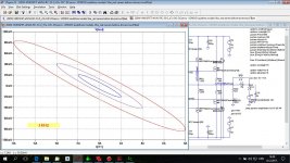
This does not reflect output impedance non-linearity. It is just OL output impedance divided by feedback factor, no level dependence shown.
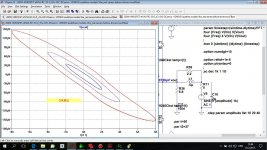
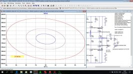
In case you are interested not only in nice plots, but also in something more useful, put the voltage generator not to the input, but to the output, via say 5 or 10 ohm resistor. Inject sine current of 1 - 10A into the output, measure current injected to the output and voltage at the output terminals of the tested amplifier. You can also make an X-Y plot of output voltage vs. injected current. Make this at several frequencies and then you will see output impedance nonlinearity.
Something like this?
Attachments
Last edited:
But the words of Olive, which you linked sayBill, possibly if listeners rated something as "bright" when JBL knew FR to be okay, the engineers might be clued in to look at harmonic distortion to see if that could explain it.
For example, Bright-Dull and Full-Thin are timbre sub-attributes related to the relative emphasis and de-emphasis of high and low frequencies, respectively
So to me that is pretty clear what people were being trained to hear, no 'possibly' about it. I don't know the good Dr.Olive so cannot ask him
In this we are in violent agreement 🙂. I could be wrong, but I suspect that the very low distortion of very accurate reproducers like the M2 is a side effect of the design, not a goal.Don't know how THD would fit in with that, especially since it is known not to correlate well with perception.
Something like this?
Yes, exactly! Very nice results. You will see that in the real amplifier even the connecting wires to rear panel speaker terminals will make a difference. Similar as in case of simulated THD x measured THD. Enough to move "Vout" node behind the output inductor in your sims.
Last edited:
Pavel have you had a chance to perform the mentioned test procedure on Upupa's amplifiers with Hawksford EC, or any other amp with EC, I assume the results from such amps differs a bit.
btw regarding the test proposed, the channel under test probably has the input grounded, yes?
Cheers Michael
ps. I hope Upupa is ok, long time no see of him.
btw regarding the test proposed, the channel under test probably has the input grounded, yes?
Cheers Michael
ps. I hope Upupa is ok, long time no see of him.
Your link supports Scott's argument not your own. In fact Dr. Olive states ' The only pertinent information not shown in this graph is how loud the loudspeaker will play before producing audible distortion (trust me, this loudspeaker will play very loud! )' .
So Like Geddes Olive sees speaker distortion as a secondary issue at best.
I assume you are all read up on Olive etal research. In it, is to the first degree --- frequency response.... flatness and extension...... Level variations from flat can be detected with low Q res as little as 0.1dB.
And, no, distortion was not an after thought in the design of the M2. Nor was the waveguide radiation pattern.
Geddes comment was that a speaker with only 2H dominating would not be much of an issue because of the masking effect. However, very few speakers have only 2H (if any exist). And many times have higher 3H.
---------
I use FFT and THD and IM to only determine the amps performance. Not to judge how it would sound. And, yes the M2 can play loudly and still be clean/low distortion and its dynamic range is amazing. But, then you also have several Thousands of watts driving them, also.
THx-RNMarsh
Last edited:
Something like this?
Hi.... what OPS idle was used in your amp's sim?
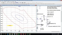
The THD tests were with 200mA idle.
-Richard
Last edited:
Sure. Test scheme attached, I have been using this method for about 10 years.
What have you learned about amp design from this type test?
Certainly layout matters ... but what about the actual design and what would be the possible audible consequences with speaker load?
THx-RNMarsh
What have you learned about amp design from this type test?
... but what about the actual design and what would be the possible audible consequences with speaker load?
THx-RNMarsh
IMO it is the test that has smallest requirements on test equipment and same time probably most revealing about power amplifiers. More than THD or IMD spectra. Easy to understand and easy to interpret. Little bit similar to distortion residual measurement. It shows what is most important for output stage linearity. Is it the number of output pairs? Or is it rather VAS nonlinear load, that may be reduced e.g. by 3EF topology? What do you think? 😉
Though number of output pairs is important, good driver and especially very light VAS load seem to be most important.
Possible audible consequences with speaker load? The more difficult speaker load, the more important are smooth and low (dv/di) curves. No spikes that would indicate to output impedance discontinuity or switching delays.
I assume you are all read up on Olive etal research. In it, is to the first degree --- frequency response.... flatness and extension...... Level variations from flat can be detected with low Q res as little as 0.1dB.
And, no, distortion was not an after thought in the design of the M2. Nor was the waveguide radiation pattern.
You posted a link to try and back up your point, which failed miserably. This does little to correct that.
Hi.... what OPS idle was used in your amp's sim?
The THD tests were with 200mA idle.
-Richard
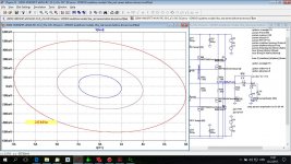
160 mA.
Damir
You posted a link to try and back up your point, which failed miserably. This does little to correct that.
No I didnt. It was what scott said - my way of agreeing. to a limited extent - which i explained.
-RNM
Last edited:
160 mA.
Damir
As you have the schematic in sim already.... how would more OPS devices change things and Vas?
I am not sure how this test can be used and the consequences of what is shown. PMA thought of some.
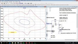
The shape doesnt bother me so much but any kinks in it does.
Does bias in OPS affect 'kinks' ?
THx-RNMarsh
Last edited:
Yes, exactly! Very nice results. You will see that in the real amplifier even the connecting wires to rear panel speaker terminals will make a difference. Similar as in case of simulated THD x measured THD. Enough to move "Vout" node behind the output inductor in your sims.
This is after output inductor. Last one was with 200 mA bias.
Attachments
As you have the schematic in sim already.... how would more OPS devices change things and Vas?
I am not sure how this test can be used and the consequences of what is shown. PMA thought of some.
The shape doesnt bother me so much but any kinks in it does.
Does bias in OPS affect 'kinks' ?
THx-RNMarsh
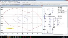
Richard, VAS is the best BJT available. The bias certainly affect 'kinks', here is with 300 mA.
Damir
Attachments
Scott, I think it was you, that link (seems to be deleted now) you posted to Breaux Freres-Ma Blonde Est Partie is the BEST music I've heard all year!
Richard, you have to do your own research and studies. You have more than enough hints now. The plots are IMO self-explanatory, just read them.
Scott, I think it was you, that link (seems to be deleted now) you posted to Breaux Freres-Ma Blonde Est Partie is the BEST music I've heard all year!
Still there one page back.
//
- Status
- Not open for further replies.
- Home
- Member Areas
- The Lounge
- John Curl's Blowtorch preamplifier part II