How would you tell if there were harmonics? Typically the closed loop distortions are well below the best analyzers today.
Maybe for a "sound-card" type analyzer, -120db would be hard to measure.
Opamp buffers would not be good enough for my purpose. I am filtering a -145db signal to -160dbv.
THx-RNMarsh
Last edited:
Maybe for a "sound-card" type analyzer, -120db would be hard to measure.
Opamp buffers would not be good enough for my purpose. I am filtering a -145db signal to -160dbv.
THx-RNMarsh
I can only see passive L/C/R helping here, or it would be standard practice. Same with digital filtering the A/D and D/A have to pass the fundamental at full scale, it makes no sense to expect them to filter out their own non-linearity.
I have seen somewhere IIRC a second filter path of opposite phase in a kind of precision current dumping arrangement, but this is tantamount to a good composite amp.
Last edited:
If anyone's in charge of a few grad students who are looking for a 2 day project, maybe you could ask them to whip together an opamp circuit design whose input stage includes ideal Schichman-Hodges "LEVEL-1" MOSFETs (perfect square law devices) as collector loads to the input stage, and an output stage with a crossover region dead zone 3xVbe wide. These ought to provide tons and TONS of harmonics, both even and odd, that are easy to measure even with SPICE simulation.
Then simulate said opamp's THD twice. First, as in Sallen Key filters, as a unity gain buffer. Second, as in State Variable filters, as an integrator. Is there any difference? How large is the difference?
Then simulate said opamp's THD twice. First, as in Sallen Key filters, as a unity gain buffer. Second, as in State Variable filters, as an integrator. Is there any difference? How large is the difference?
I think I'm the closest to working with grad students here, and they're far more interested in avoiding simulations wherever possible. 🙂
the little triangle symbol isn't a suicide pact
how many times does it have to be said - use composite amplifier techniques
if you need 2-4 monloithic op amps or disrete add ons it will be straightforward at the level of competence of several players here - if not commonplace or trival depending or required performance
Opamp buffers would not be good enough for my purpose. I am filtering a -145db signal to -160dbv.
how many times does it have to be said - use composite amplifier techniques
if you need 2-4 monloithic op amps or disrete add ons it will be straightforward at the level of competence of several players here - if not commonplace or trival depending or required performance
Last edited:

OT posts removed. Keep it on topic guys, there are plenty of other places to discuss that kind of stuff.
how many times does it have to be said - use composite amplifier techniques
if you need 2-4 monloithic op amps or disrete add ons it will be straightforward at the level of competence of several players here - if not commonplace or trival depending or required performance
show me an example circuit with low enough distortion.
THx-RNMarsh
the inverting amp in the 1st post is a good start - output could be beefed up with DSL driver CFA output biased in Class A - faster op amps allow more 20 kHz loop gain
there are better input op amp options too - BJT or FET input
Dimitri Danyuk's unity fgain power supply bootstrap circuit should give much lower distortion at reasonable input Z - the measured distortion is for large unbalanced Zin
again its quite likely as you get down in the weeds that ouput op amp output Class A bias eases managing layout by linearizing PS currents
there are better input op amp options too - BJT or FET input
Dimitri Danyuk's unity fgain power supply bootstrap circuit should give much lower distortion at reasonable input Z - the measured distortion is for large unbalanced Zin
bootstrapped supply composite op amp + buffer - reduces even the input stage nonlinear common mode impedance
http://www.epanorama.net/sff/Misc/O...g to reduce distortion in op-amp circuits.pdf
Supply Bootstrapping Reduces Distortion In Op-Amp Circuits | New operational amplifiers optimized for high-performance audio and ultrasound applications combine extremely low total harmonic distortion plus noise (THD+N), -130 dB, with large output vo
I recommend looking beyond "buffer" IC with fixed internal unity gain - more options are available in CFA op amps designed for DSL driver applications - I've used the TPA6120 which is a audio speced version of the THS6012 for composite amp output stages
CFA op amps can be used unity gain with a feedback R - you can even size the R value to "overcompensate", increase stability margins
again its quite likely as you get down in the weeds that ouput op amp output Class A bias eases managing layout by linearizing PS currents
Last edited:
I would first challenge someone to build a useful lab test bed that would make repeatable -160dBV measurements over say 3 decades in frequency and get the same answer every day. I'm not talking bridge or null measurements, I mean -160dBV measurements in the presence of 0dBV signal.
The Radiometer Copenhagen CLT-1 and its successor the Danbridge CLT-20 http://www.danbridge.com/datasheet/instruments/CLT.pdf can do that at one frequency, 10 KHz. Beyond that there seems to be nothing commercially available. I don't think its practical to duplicate that method for lower frequencies. The inductors and transformers in it are the size of bowling balls for 10 KHz.
I mean -160dBV measurements in the presence of 0dBV signal.
10 ppt. Now there is a challenge.
If y'all figure it out, let me know, I'm betting I could put it to good use with some of my work. 😉
my measurements have been indirect, 1 kHz IMD difference frequency - certainly full 80 kHz audio THD would be very hard
but there seems to be reason to believe performance better than -140 dB is available over audio with composite op amp techniques
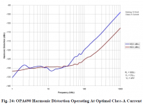
I believe I could wrap another 30-40 dB loop gain around the Class A biased OPA690 below 100 kHz which was measured in: http://citeseerx.ist.psu.edu/viewdo...C6C99448?doi=10.1.1.138.299&rep=rep1&type=pdf
but there seems to be reason to believe performance better than -140 dB is available over audio with composite op amp techniques
I believe I could wrap another 30-40 dB loop gain around the Class A biased OPA690 below 100 kHz which was measured in: http://citeseerx.ist.psu.edu/viewdo...C6C99448?doi=10.1.1.138.299&rep=rep1&type=pdf
Attachments
Its an interesting measurement technique but not new. In this implementation they don't mention the nonlinearity of the delay line. You get the sense that its perfect. One caution would be that the delay line an dphase shift may not match the opamp at all harmonics and levels. Do you need to tweak for a null at easy measurement and harmonic? However -130 to -140 dB harmonics are quite measurable using less involved techniques. -160 is still very difficult since its the realm of passive component nonlinearity. I'm also a little skeptical of the effects of the series filter into the summing amp. it should have little impact but remains unknown.
Piling on extra gain to make a composite amp also makes stability extremely difficult to get. B Hofer said he took a lot of time to get the composite amps in the APx555 working. That would suggest is a non-trivial undertaking. The ones in the famous AP app note are really tweaky and only work at one frequency.
Piling on extra gain to make a composite amp also makes stability extremely difficult to get. B Hofer said he took a lot of time to get the composite amps in the APx555 working. That would suggest is a non-trivial undertaking. The ones in the famous AP app note are really tweaky and only work at one frequency.
The Radiometer Copenhagen CLT-1 and its successor the Danbridge CLT-20 http://www.danbridge.com/datasheet/instruments/CLT.pdf can do that at one frequency, 10 KHz. I don't think its practical to duplicate that method for lower frequencies. The inductors and transformers in it are the size of bowling balls for 10 KHz.
yes, which is why I am looking for alternatives to passive filters. But if I have to, I will try. If Shibasoku can measure that low on monitor/FFT output, then I can test the filter.
THx-RNMarsh
Last edited:
I think the input amp on the Shibasoku would need some careful trimming/adjusting to get that low. Or you could bypass it and go directly to the band elimination filter if you can figure out how to trick the AGC circuits. -160 is a very lofty goal.. Also at least 40 dB beyond anything conceivably audible.
The instrument measures very accurately directly to -130dbv. The -160 exists at the monitor port and using FFT. We just went over that when measuring davids generator at -145dbv level with the instrument.
THx-Richard
THx-Richard
Last edited:
10 ppt. Now there is a challenge.
Except that keeps being the goal, I continue to not understand why things like Bob Cordell's distortion magnifier or even the technique Pease showed on their audio op-amp data sheets are shunned. With careful component selection bridge and null techniques just win. Brute force does not give a better answer.
B Hofer said he took a lot of time to get the composite amps in the APx555 working. That would suggest is a non-trivial undertaking.
One comment he made on this was that he had to use separate regulated supplies for the two opamps in the composite as at that level even minuscule mutual interference through the supplies had an impact on the distortion.
He didn't detail explicitly but I think he also tweaked the separate supply voltages to get to each opamp sweet spot.
He said it was the hardest thing he did in his long career, which means I have no chance ;-)
Jan
- Status
- Not open for further replies.
- Home
- Member Areas
- The Lounge
- John Curl's Blowtorch preamplifier part II