Same amplifier, configured (a) as unity gain buffer; (b) as integrator:
Total Harmonic Distortion: 5.754084%(6.259402%)
********************************************************************************************
Total Harmonic Distortion: 4.513268%(5.040482%)[/CODE]
______
5-6% !!!
Keep trying.... at least -120 should be expected with best opamps.
THx-RNMarsh
I think this illustrates that the integrator doesn't reduce the native distortion of the opamp. At -160 dB assuming you have an active circuit that clean the passives around it will still limit the performance.
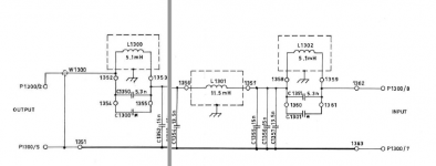
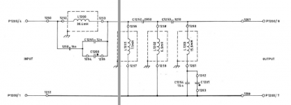
CLT-1 filters. This is a passive way to get to -160dB. As usual the circuit doesn't show how difficult it is to make passive components to do this.
Attachments
I think this illustrates that the integrator doesn't reduce the native distortion of the opamp.
That's what I think, too. Perhaps Jan Didden, who advocated integrators, has an opinion about it.
I think this illustrates that the integrator doesn't reduce the native distortion of the opamp. At -160 dB assuming you have an active circuit that clean the passives around it will still limit the performance.
I'll believe it when I see an accurate model result.
-RM
CLT-1 filters. This is a passive way to get to -160dB. As usual the circuit doesn't show how difficult it is to make passive components to do this.
I've already synth the filter and show similar very large L values. Not a deal breaker but looking for something else, if it exists.... maybe a hybrid. ??
THx- RNm
I'll believe it when I see an accurate model result.
-RM
The model has little to do with it, a weak non-linearity enclosed in a feedback loop fairly basic stuff, maybe jcx or Waly could walk us through it.
To get >5% THD (so that simulator truncation, rounding, etc are negligible), I had to include a fairly large and not-weak nonlinearity.
Remember that a perfect triangle wave, when fed into a THD analyzer, records about 3% THD, and yet nobody would say "that's a moderately decent sinewave". Mine is a lot worse than that.
Remember that a perfect triangle wave, when fed into a THD analyzer, records about 3% THD, and yet nobody would say "that's a moderately decent sinewave". Mine is a lot worse than that.
Geeez.
It might be just as fast to take an opamp and test it for harmonics with and without C in nfb.
THx-Richard
It might be just as fast to take an opamp and test it for harmonics with and without C in nfb.
THx-Richard
Last edited:
That's what you have in a state variable filter. It attenuates harmonics from upstream sources but not particularly from the opamp itself. It can exacerbate harmonics by demanding more current at a point in the waveform that where the crossover nonlinearities are highest.
I dunno, final result 60 minutes after deciding to try it, might be the least possible time.It might be just as fast to take an opamp and test it for harmonics with and without C in nfb.
Least possible effort, on the other hand, is to sit still and hope someone else does the work.
in this case post #1462, #1463 and #1467 underScott, Dick Burwen USED the 911 IC, he didn't design it. He would select out from a number of 911 IC's and put them in a HYBRID MODULE with a few surrounding passive that he sold to Mark Levinson.
The Harris 911 had a true PNP internal transistor. Check it out, this IC was made with an alternate process, that is WHY it was so expensive at the time. It was made from radiation sensitive environments. Please check things out first. The HA911 was a pretty darn good part, sometimes. It also often suffered from Xover distortion, but if you selected them out, they were reasonably OK.
http://www.diyaudio.com/forums/everything-else/169484-what-wrong-op-amps-147.html
is also of interest.
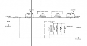
Which has lowest thd on output if signal is at corner freq of filter?
-RM
View attachment filter vs filter.pdf
.
-RM
View attachment filter vs filter.pdf
.
Which has lowest thd on output if signal is at corner freq of filter
.
Your picture is wrong the circuit on the right can never have gain less than 1 and can never reduce the op-amps distortion below that of it used as a follower.
yes. pooped. its quick conceptual.....scott. use appropriate topology. and it IS the topology I am/was asking about. yesterday, I did throw an opamp onto breadboard --- signal to inverting input.... gain less than 1.
However, Any specific suggestions? Need steeper slope, too.
-Richard
However, Any specific suggestions? Need steeper slope, too.
-Richard
Last edited:
Not toooooo concerned about noise at the moment for this app. Noise from LP output stage will be OK. Using FFT only.
-RM
-RM
The point is you can never get below g=1 noise gain from the feedback loop. At all frequencies. Therefore, any harmonic removal of the now-added opamp must come from a downstream passive filter. (The newly added opamp/filter CAN knock down upstream harmonics generated from prior stages, obviously)
However, Any specific suggestions? Need steeper slope, too.
Air core L's and the best C's keep the L's several feet away from metal with any magnetic hysteresis. Putting a diagonal cutter next to one of mine caused odds at the -145dB level.
You are asking for essentially what is impossible any active filter will have it's own distortion appear at the output depending on the noise gain at that frequency. You do realize DPH's use of the term noise gain had nothing to do with noise?
Air core L's and the best C's keep the L's several feet away from metal with any magnetic hysteresis. Putting a diagonal cutter next to one of mine caused odds at the -145dB level.
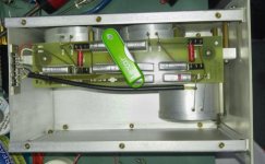
Attached is a picture of the CLT-1 low pass filter. You can see the three coils inside their aluminium cans. I believe there are ferrite pot cores inside. The USB stick is for scale. This filter is tuned to remove the third harmonic of a very clean 10 KHz sine wave with up to 1W passing through. For a 1 KHz filter I guess the coils will be 10X the size?
In the CLT-1 manual they say a lead pencil tip next to a lead wire can cause harmonics.
Attachments
- Status
- Not open for further replies.
- Home
- Member Areas
- The Lounge
- John Curl's Blowtorch preamplifier part II