Aside from the absolutely fascinating processes involved, one thing struck me, when the mastering engineer said: 'You know, we get the master files, either digital or a tape, and then I listen to them, and add a bit base or some presence, maybe dim too bright highs until it sounds right to me, before I cut it."
He did say that normally he checked back with the customer if they agree to his changes, but it puts the effort of the recording engineer in a different perspective.
Jan
Well there are grammys for best mastering each year. Always wondered how you judge the input of the mastering vs recording and mixing. But yes the mastered output is often NOT what the artist signed off. Which is sad.
A little touch up is not a bad thing. usually it is due to the recording mic characteristics used and its placement. Especially its off-axis response and placement. A slightly off center mic can make highs dull. This is where a Mastering engineer's listening ability is needed rather than only as a technical processing person. But he doesnt do the producers EQ, balance, mix et al. Just touch up.
If he/she has to go back to the source for approval, it was either the producers idea to sound that way or a bad recording and more correction was needed in the Mastering Eng opinion....... and he/she listens to Lot of recordings.
THx-RNMarsh
If he/she has to go back to the source for approval, it was either the producers idea to sound that way or a bad recording and more correction was needed in the Mastering Eng opinion....... and he/she listens to Lot of recordings.
THx-RNMarsh
Last edited:
I was considering getting one of those. Conrad Hoffman shows they can be useful for lots of things, and signal input is a very useful feature too. Just not sure how to choose a good one.
I think you just get the particular one you get... then fix it, if it needs fixing. It's tubes, so probably tubes, caps, resistors, connections/switches - in that order for failures. The switches are rather good, so some deoxit ought to work. Otoh, it may work as it arrives.
The schematics are available online, free, afaik.
The military one is very nice, as is this particular model - as far as newer and other brands, dunno. Since these are not huge like some others, and they work well, that's what I have gone with.
A friend turned me on to these a long number of years ago when he showed up with one and we were able to match caps within 1% with no trouble at all... and I think it measures ESR - iirc.
Otoh, for just random checking I use the function on the multimeter... which also does inductance - I pull this one out when there's "serious" measurements to be made, which is actually infrequent.
But it does have a "magic eye tube" and a "galvanometer" type meter.
_-_-bear
PS. got a link to where Conrad Hoffman talks about them? Curious now.
It seemed like common sense using my signal generator and a Kelvin connection, you're just measuring impedance after all. I mainly want at least 5nH resolution. However it is not portable. I would be surprised if someone has not worked out how to make useful measurements in an inexpensive dedicated device.
Meant to inquire - what is it that you are measuring that you need such resolution? That "n" is a "nano" not an "m" as in milli, yes? Or maybe that's some strange Euro/British nomenclature that is foreign to me? 😀
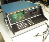
ESI Videobridge!
Heh! Wow Demian, how incredibly cool retro computer-age!! Think of the TTL chips inside!! Cool. And the TAPE DRIVE!! Sweet! And it works too!
Love it! 😀
Heh! Wow Demian, how incredibly cool retro computer-age!! Think of the TTL chips inside!! Cool. And the TAPE DRIVE!! Sweet! And it works too!
Love it! 😀
Attachments
Last edited:
Actually I have 3. Spares so I dont need to worry about repair.
Its S100 based internally with a Z80. Really vintage but as accurate as any current instrument. And repairable.
Only one has the tape drive. One is a later model with measurements to 100 KHz.
Sent from my LG-H811 using Tapatalk
Its S100 based internally with a Z80. Really vintage but as accurate as any current instrument. And repairable.
Only one has the tape drive. One is a later model with measurements to 100 KHz.
Sent from my LG-H811 using Tapatalk
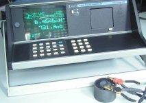
And with measuring clips shorted?
I simply do not believe in those math, .4646... some "floating point" error in co-processor, starving for extra bits?
IMHO, there is simply two ways..boring electronic(also with very nonperfect components, noise dirty, also with unacceptably complicated math for design... ), simply, only for engineers, and other way, interesting "audio" quantum processes, a lot of purity, unknown technology and a lot of imaginations...
This should be learned from begining...
And a diverted approvements for both "ways" 🙂
And with measuring clips shorted?
I simply do not believe in those math, .4646... some "floating point" error in co-processor, starving for extra bits?
Well anyone who knows what they are doing knows how many SF to take in a measurement from their instrument. Part of basic training in how to measure things. So what is your point?
Let "anyone" to answer..🙂
This inductivity precission at display with this measuring cables? This is not in all "measuring cookbook"
BTW, rf noise in air, years 1970-80, and noise in 2016..?
Point more clear?
This inductivity precission at display with this measuring cables? This is not in all "measuring cookbook"
BTW, rf noise in air, years 1970-80, and noise in 2016..?
Point more clear?
Leave my bad English aside. I am to old for gramatic purification.🙂
Yup🙂, there is a lot of details in measurement. From calibration(reference inductor is expensive), to usefull writting shown on display.
And necessity for a batch of numbers behind decimal point, for inductors?
P.S.
I have sentimental feelings for such gadgets..as for my student age...
But,they are for special place in my room, not for measurements..
Last edited:
Note that is a random picture, not Demian's setup. He has been in the game long enough that if he says this tester is accurate, I believe him. If you wrote off every instrument that had a display with more DP than you thought reasonable that would be a lot of stuff you wouldn't use, new as well as old.
You miss the point...
Accurate-believe..I don't see the connection?
I do not believe in my lab instruments, from yesterday.
Accurate-believe..I don't see the connection?
I do not believe in my lab instruments, from yesterday.
All you have to do is to round up to 6.5mH, and the calibration is moot!
We used to have the same problem with early calculators. Where did 8-9 places get you? We had to ignore the extra digits, until later calculators would let you round them to just 3-4. Accuracy is important, but in this case, not that important.
We used to have the same problem with early calculators. Where did 8-9 places get you? We had to ignore the extra digits, until later calculators would let you round them to just 3-4. Accuracy is important, but in this case, not that important.
More than you would want to know about the videobridge ESI 2160 Video Bridge (Auto LCR Meter)
Basic accuracy 0.02%
3023 test frequencies ranging from 20 Hz - 150 KHz
It has a self calibration built in.
Basic accuracy 0.02%
3023 test frequencies ranging from 20 Hz - 150 KHz
It has a self calibration built in.
Demian,
How much difference would there be for an inductor you were using for a cross-over network in reading between let's say 100hz and say 2.5Khz, enough to worry about the shift from measuring with a variable frequency? Would the value shift enough to be more than a very small percentage of the reading or are looking for the difference between 100hz and 150Khz to see a significant shift in inductance?
Still waiting for your call.
Last edited:
Depends on the coil. One wound with solid core wire could be pretty significant. I was using custom inductors wound with Litz wire on the last passive crossover (years ago). You need to get Litz wire suitable for a frequency 5 to 10X your target crossover and the system works much more like you would expect. None of the commercial "litz wire" or foil inductors had as high a Q at the crossover. Easy to quantify with the Videobridge and measurements of the final network.
All you have to do is to round up to 6.5mH, and the calibration is moot!
We used to have the same problem with early calculators. Where did 8-9 places get you? We had to ignore the extra digits, until later calculators would let you round them to just 3-4. Accuracy is important, but in this case, not that important.
Apsolutely!
I would rather to see parasitic capacitance for inductors(or Q factor), instead for digits accuracy inductance.
Well, now that we have the test equipment sorted out, perhaps we can go back to discussing hi end audio tweaks in a good way, rather than the approach used on other threads. I'm working with the newest Bybee devices myself. Good things so far. How about the rest of you?
Just took delivery on a bunch of SMD JFETs and a test jig to sort them. Jig uses the delightfully inexpensive LMC6482 (link to datasheet) with 0.02 picoampere input bias current. I am measuring Vpinchoff while forcing Ids=60 nanoamps. That's where I ran out of guts, worried about leakage from fingerprints, humidity, etc. JFET datasheets measure Vpinchoff at 3 nA but I don't have the guts to try it. Am expecting that the delta_Vpinchoff between two units, both measured at 60nA, is equal to the delta_Vpinchoff between those units measured at 3nA.
Why 60 nA? That's the knee of the price-vs-megohms curve for through hole resistors at DigiKey.
Why 60 nA? That's the knee of the price-vs-megohms curve for through hole resistors at DigiKey.
- Status
- Not open for further replies.
- Home
- Member Areas
- The Lounge
- John Curl's Blowtorch preamplifier part II