I assume you are playing with standard recording mics the metal diaphragms of standard measurement mics are not mechanically optimal for noise
I have a measurement mike in front of me that was not as spectacularly quiet as the B&K you mentioned, but I measured it at 4.8dB(A), which ain't bad.
The B&K reference has the gap for the 4133 listed in it in the article on stability. I read somewhere else that under polarization 1/2 of the gap goes away. The manual says max 250V.
Recording mike capsules are different and usually use plastic diaphragms. The max operating voltage should be specified from the capsule vendor. There are a few in China that serve most of the market today. You can still get Neumann or, probably better, the Gefell capsules.
If I were designing a microphone I would use an FM technique like Sennheiser. With no DC the diaphragm is not tensioned by the polarization and you can get the electronics noise below that of the capsule (or so Keith Johnson explained to me). It would be easier today since the RF parts are far more available and smaller.
Thanks for the added input Demian. It is probably better to stay within the max recommended. I use variable bias voltage up to 200V with my B&K 1''.
Scott,
You %#}~¥¥!!,!! One of the secrets of using a measurement microphone is that you don't point it at the sound source! When you see the pictures of pros using a microphone it is on a stand and up at an angle of 70 degrees. I always love to watch folks other than mine point the microphone at the loudspeaker they are tuning. Next you will let the cat out of the bag about ground bounce.
Last week I had my guys running measurements in the back and when they mentioned an issue at XXX hertz wasn't tuning properly I just told them to move the microphone a few feet. That solved the tuning issue.
One of the sharper house guys was watching JJ and I tuning a stadium. He was noting what we adjusted and what we ignored. He then related watching other folks use a single microphone placement and tune for as flat a line as possible on their measuring apparatus. The results almost always were horrible.
The only good take away from that B&K issue was they used 1" microphones. The problem is less with 1/2" ones.
Now please quit giving away professional secrets.
Demian I suspect an RF approach with a sputtered plastic diaphragm is not going to be stable enough under extreme operating conditions.
Yes FM makes sense, although one pair I had borrowed was quite noisy, probably defective. Also I believe they were Sennheisers.The B&K reference has the gap for the 4133 listed in it in the article on stability. I read somewhere else that under polarization 1/2 of the gap goes away. The manual says max 250V.
Recording mike capsules are different and usually use plastic diaphragms. The max operating voltage should be specified from the capsule vendor. There are a few in China that serve most of the market today. You can still get Neumann or, probably better, the Gefell capsules.
If I were designing a microphone I would use an FM technique like Sennheiser. With no DC the diaphragm is not tensioned by the polarization and you can get the electronics noise below that of the capsule (or so Keith Johnson explained to me). It would be easier today since the RF parts are far more available and smaller.
The same guy who had bought the Sennheisers from a widow at a church sale also loaned me a pristine pair of tube U47s. For the two pairs of mics, an Ampex luggable, stands, cables, and some Peerless mic transformers, he paid ten dollars. I suspect a distinct rumbling could be heard from her late husband's grave.
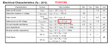
Depends on the manufacturer I suppose. Here are three of them: Toshiba, Moto / ON Semi, and Fairchild. What I see here is nanoamps.Obviously the difference between your 60nA and the manu's 1uA are substantial.
_
Attachments
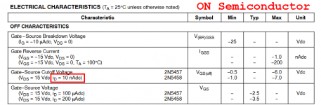
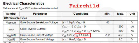
Id is a forced condition, not measured.
Forcing current below 1uA can be problematic in high speed ATE.
Forcing current below 1uA can be problematic in high speed ATE.
... I am measuring Vpinchoff while forcing Ids=60 nanoamps. That's where I ran out of guts, worried about leakage from fingerprints, humidity, etc. ...
Id is a forced condition, not measured.
In my little jig, Ids is forced not measured. Yes.
Depends on the manufacturer I suppose. Here are three of them: Toshiba, Moto / ON Semi, and Fairchild. What I see here is nanoamps.
_
OK you have 1, 10, and 100nA try all 3 on the same FET so what's the Vp to plug into the Id vs Vgs equation at 500uA? I happen to have the stuff on my desk today maybe I can try this.
I have a measurement mike in front of me that was not as spectacularly quiet as the B&K you mentioned, but I measured it at 4.8dB(A), which ain't bad.
I published B&K's own data in LA Vol. 1 on the 4145, 4144 1" capsules, not that quiet (25-40nV over the whole audio band).
OK you have 1, 10, and 100nA try all 3 on the same FET so what's the Vp to plug into the Id vs Vgs equation at 500uA? I happen to have the stuff on my desk today maybe I can try this.
Good, please do. In my case I am sorting transistors, not fitting model parameters. All I need at the moment is a few conveniently measured quantities that help me partition the pool of devices into groups-of-alike-parts. Thus far, using just two pieces of data per transistor (Vgs60nA, Idss10V), seems to be doing an acceptable job.
If I were designing a microphone I would use an FM technique like Sennheiser. With no DC the diaphragm is not tensioned by the polarization and you can get the electronics noise below that of the capsule (or so Keith Johnson explained to me). It would be easier today since the RF parts are far more available and smaller.
Try to find Baxandall's article, the noise comes from the Q of the capsule in the RF circuit. Eliminating the bias resistor noise gives one a degree of freedom in achieving nearly the noise of the acoustic circuit alone.
One of the secrets of using a measurement microphone is that you don't point it at the sound source! When you see the pictures of pros using a microphone it is on a stand and up at an angle of 70 degrees. I always love to watch folks other than mine point the microphone at the loudspeaker they are tuning.
Well, let me expand on the angles during measurements with:
If you are far from the source, you would use a microphone designed for flat random incidence response. If you measure close to a source (speaker) then you use a microphone which is designed for flat (0 degree) incidence response.
A microphone designed for flat (0) incidence response can approximate the random response if aimed at 70 degrees to the nearby source.
A mic designed for flat random incidence response used close to the source should be turned at 70 degrees to avoid the rising on-axis response of such a mic.
For measuring freq response, it is a lot better to use 1/2" or 1/4" Both their on and off-axis is flatter to higher freq and thus more universal mic.
The one inch results can be compared to a standard WE640 standard. But, for our purposes the smaller diam are best for measurement. Otherwise, use the appropriate mic for the application.
THx-RNMarsh
Last edited:
I published B&K's own data in LA Vol. 1 on the 4145, 4144 1" capsules, not that quiet (25-40nV over the whole audio band).
The impressive thing was that this was a 1/2" mike, steel diaphragm, and decent bandwidth. The tradeoff was distortion at high level.
It was not trivial to measure this- I did a variant of your sand and barrel trick, real hillbilly science.
edit: And I should mention that the cable from mike to preamp actually made a difference.
The impressive thing was that this was a 1/2" mike, steel diaphragm, and decent bandwidth. The tradeoff was distortion at high level.
That makes sense. In B&K's usual full disclosure mode they published a paper on the techniques to do this, one being the slackening of the diaphragm Going to 1/2" from 1" getting ~6dB more noise and 2x the BW seems believable.
Good, please do.
The effect was quite large for a couple of 2SK222's that I tried .304V and .253V Vp when fit from 100uA to Idss to the standard square law model and .482V and .435V Vgs at 50nA.
There are also the articles from Sennheiser in the early 60's regarding the design of the early MKH105 and MKH405 RF cndensors in the JAES. Don't remember the exact dates.
Alan
Alan
RNM,
The current term is "Free Field" for the microphone you point at the source. I have both the 4145 and 4155 Bruel and Kjaer versions of these. (Purchased with the meters!)
For all the details
http://www.bksv.com/doc/br0567.pdf
The current term is "Free Field" for the microphone you point at the source. I have both the 4145 and 4155 Bruel and Kjaer versions of these. (Purchased with the meters!)
For all the details
http://www.bksv.com/doc/br0567.pdf
I am using the terms first used in the literature for if anyone wants to look up the subject far back to its origins.
I'll check on those mics.... Both are for an environment far from the source and in a reverberant (diffuse field) field. You are correct to use those at 70 degrees angle away from the nearest strong source (direct or reflection). Otherwise the on-axis (0) peak will skew the results.
However, to be without corrections or peaking a more omi-directional mic would be more accurate for reverberant spaces (not close mic'ed to a speaker). This happens naturally with the smaller diameter mics (<1/2") but best to use a mic that has flat random incidence response past 20KHz with minimal peaking at any angle. A suitable diffuse field mic would be B&K: http://www.pcb.com/contentstore/mktg/LinkedDocuments/Acoustics/TM-AC-377A21_LowRes.pdf
THx-RNMarsh
.
Last edited:
I think the differences between random, free field and pressure response have to do with the tuning/tensioning of the diaphragm. The response vs angle is a physical phenomena that comes from the diameter of the diaphragm. It would be present in all three types. If your system has the ability to put the appropriate correction curve you can use a pressure response for free field or vice versa. In some cases (e.g. 1/4" pressure response) the impulse response will be better since the tuning is not peaked to get the extra HF boost for free field.
B&K made a special grid (UA0055) to correct for random incidence. I have one and its a cute bit of stainless for the 1" mike. Its mentioned in the writeup linked above. Not useful above 10 KHz or so. The author of the electrostatic calibration article is the principle behind GRAS. He was/is the real expert on the technology.
Random incidence really means that if the source is really random, as in all directions (lots of hard surfaces), it will average the boosts from some angles with the rolloffs from other angles. I would just use a 1/4" mike if its important.
- Status
- Not open for further replies.
- Home
- Member Areas
- The Lounge
- John Curl's Blowtorch preamplifier part II