Troublemaker.
Do we reeeaaaallly wanna go down that path again?? 😕 😕 🙂
microdiodes...sigh
John
Nah. We already know where that path leads.
se
You see, it’s never OK 😀
Ed and Scott
Buzz is the proper word for what I have experienced with the through the transformer core capacity coupling btn live and chassis.
Ed I am all for using words which have a definite meaning. Makes for a positive communication.
It's also my understanding that hum is almost always a result of magnetic coupling ( if not entirely a result of mechanical coupling from a vibrating transformer). And buzz almost always a ground loop issue
https://www.dropbox.com/s/snli120yfug1aiw/Copy%20of%20hum.wav?dl=0
https://www.dropbox.com/s/mmlutbaavng31bg/Copy%20of%20Buzz.wav?dl=0
George
George
Ground loops are often explained as a loop that couples to a magnetic field. But more often when you have two paths the resistance is a bit different and so they end up being a voltage divider. I avoid using the term ground loop as I have only once seen a loop big enough to actual have enough coupling to cause a significant hum. The solution was to cut one wire.
I do try to use loudspeaker, audio power amplifier etc to be clear. When I use noise it is a general case of an undesired signal. 1/F or thermal noise are also specific terms to be used when applicable.
I also suspect that you notice the buzz noise we are discussing when it is above the threshold where it is clearly different than noise. I suspect the next time uou play with it you may notice at lower levels it is more random noise like.
Have you also had the cases where rfi is causing increased noise?
A ground loop can be the aggressor, the victim, or both. In your realm, they must couple to a time varying magnetic field. In my field of endeavor, static magnetic fields come into play as well.Ground loops are often explained as a loop that couples to a magnetic field.
Huh?But more often when you have two paths the resistance is a bit different and so they end up being a voltage divider.
You detailed a current divider, then said voltage divider. Can ya draw us sumptin splainin what youz means?
To quote Harry Callahan..."you're a good man" (ps, thanks for that low hanging fruit, I appreciate the opportunity... 😀I avoid using the term ground loop
There goes your lightning protection, but now you have a spark gap....... as I have only once seen a loop big enough to actual have enough coupling to cause a significant hum. The solution was to cut one wire.
John (the troublemaker)🙄
George
Ground loops are often explained as a loop that couples to a magnetic field. But more often when you have two paths the resistance is a bit different and so they end up being a voltage divider.
With ground loop formation we see both of these effects.
I avoid using the term ground loop as I have only once seen a loop big enough to actual have enough coupling to cause a significant hum.
This means you are always doing neat layouts. This is not the case with me.
The solution was to cut one wire.
Then, was it a matter of size or a matter of form, thus function?
I also suspect that you notice the buzz noise we are discussing when it is above the threshold where it is clearly different than noise. I suspect the next time you play with it you may notice at lower levels it is more random noise like.
I have played back the buzz wav. file many times, progressively lowering the volume. Up to the point of just detectable sound, what I hear is not like random noise. Below that I can not hear it ,so what can I say?
Have you also had the cases where rfi is causing increased noise?
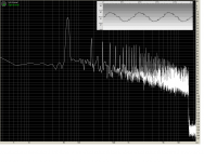
Rfi is always present within the buzz. Buzz has all the odd harmonic components of the main’s fundamental plus rfi that the loop picks up from the environment. You can see the spurae along the buzz waveshape.
George
Attachments
even if we have no commercial stake in what we are looking at.
LOL!!!!!! So you're both in the insurance business now?
smdh
For my knowledge noise can be everything added to the signal - so the spectral content and the sound can be anything. On the other hand, the sound spectrum of random noise (white, pink) is well defined and can be easy identified by listening tests.
Hum is for me something like 50/60Hz more or less sinewave, with little harmonic content.
Buzz might by heavily distorted hum, for instance rectified mains voltage, current spikes of rectifiers or leakage current of wall warts. This is often high-pass filtered, thus lacking fundamental and the low harmonics.
All in all these labellings are not strict so verbal descriptions are problematic. Whenever somebody mentions a strange noise, I would recommend to share a sound sample to make identification easier.
just my 2c
George
I expect significant high pass filtering of the noise under discussion due to the mechanism that produces it. The buzz file that I must admit I have not looked at if normal is line frequency with the hsrmonucs falling off by 3 dB per octave.
J
The wire cut was inside the chassis where the designer routed a second common ground wire back to the input and on the other side of the power transformer.
Virtually all of the dual wired ground schemes with a buzz I have seen are because the shield connectors without connections have a voltage potential between them.
We have discussed the old standard of driving a dedicated ground round and connecting all of the audio equipment to it. The neat thing was that the thicker the ground wires the less the hum/buzz. But of course it always was there. Losing the ground system that often ran parallel to the safety ground of course if the rest was wired intelligently would eliminate the issue. The new problem became where to find intelligent folks who had anything to do with audio.
Simon, my transformer has identical capacitance L/N. Oh well... I'll check on the next thing I make.
more transformer specific.... windings as Simmon has described are those with pri and seconday wound on top of each other. Now a side-by-side pri and sec wound transformer might have equal C to the core/case.
The side by side windings would be prefered for this and other reasons if you were creating your own BOM. But finished goods can be wound either way.
THx-RNMarsh
The side by side windings would be prefered for this and other reasons if you were creating your own BOM. But finished goods can be wound either way.
THx-RNMarsh
Wow Richard! Can you share some details of the build? Looks fantastic
🙂
The heat sinks are going to be over-kill but avail from other amp projects.
The work is being done for me. No surprise there, right? And, there will be a batch made to cover everyone's costs and more. Could go viral after that. Wouldnt that be great. Anyway, I do not have a complete cost to make a stereo amp.... working from an estimate. There will be amps available to purchase after they get done with mine. The design and manufacturing team filling in the blanks (over-load protection, turn-on delay,mechanicals etc) are experienced in audio design and high quality builds for low to medium size productions. [they have done high volume before and didnt like it]
I have produced a Time Line for them and they tell me they are still on track for Nov delivery. I will be there in Oct-Nov to check them out.
That is all I can tell you now unless you have something specific.
Thx-RNMarsh
Last edited:
RNM,
Is that Dadod's CFA design?
Yes. Dadod's is the only CFA from here that I heard and measured and which met all my criteria. it is better than what I am using now by a long shot (A Marantz CFA). With the new HD speakers coming, I need to upgrade my amps.
-RM
Last edited:
Have you investigated the DER EE DE-5000? It's a handheld LCR meter, sold on Amazon. I bought mine new on eBay, from a seller with budzillions of positive feedback, because I got a lower price and more add-on fixtures + test leads + gimmicks than Amazon offered.
It ain't no 1970s era HP tabletop instrument and it ain't priced that way either.
It ain't no 1970s era HP tabletop instrument and it ain't priced that way either.
Simon, my transformer has identical capacitance L/N. Oh well... I'll check on the next thing I make.
These are the currents in uA I measured on a few transformers. Sorry for the messed up table, just the way this software works.
AC Normal+Safety Gnd to frame, AC Flipped+Safety Gnd to frame, AC Normal+Safety Gnd to Center Tap, AC Flipped+Safety Gnd to Center Tap
R Core 19.3 3.3 18.9 2.7
Toroid 8.3 7.3 9.6 17.1
14A-20-24 1.6 0.9 2 1.2
PC-24-1000 2.8 5.3 3 1.3
DST-6-24 1.9 1.2 2.4 1.4
LP-24-1000 2.3 1.1 2.3 1.2
Model numbers are Signal transformers.
As you might be able to see for a good transformer the difference is quite small. The problem with measuring capacitance directly is there is not enough inductance to isolate one terminal from the other. In measuring conductance at 1,000 hertz the difference is barely seen. So the best way is to measure leakage center tap to neutral and flipping the input plug.
It is actually quite difficult to measure a potential difference between two points in a time varying magnetic field environment. How the leads of the test equipment are layed out will determine the trapped flux total. As such, the statement that you have measured a "potential" has no useful meaning, although it does point out that you do have a trapped magfield problem.J
The wire cut was inside the chassis where the designer routed a second common ground wire back to the input and on the other side of the power transformer.
Virtually all of the dual wired ground schemes with a buzz I have seen are because the shield connectors without connections have a voltage potential between them.
As to buzz, the source has to be determined. The circuit will trap buzz differently with a shorted input as opposed to connecting input grounds together (single ended), and through pin 1 differential. If you short two grounds together via external cabling, that opens up the "aggressor" field significantly.
We have discussed the old standard of driving a dedicated ground round and connecting all of the audio equipment to it. The neat thing was that the thicker the ground wires the less the hum/buzz.
Recall back in 2013 I planted ground loop info in my gallery. It details how the conductive ground loop currents create a magfield which opposes the aggressor field. The more conductive the shielding ground, the less intrusion.
A secondary dedicated ground is worse than useless, it can compromise system susceptibility to external events.
The vast bulk of the folks are intelligent. It is best not to confuse lack of EMI/EMC knowledge with lack of intelligence.The new problem became where to find intelligent folks who had anything to do with audio.
Whoa, measuring nH levels is not easy. It requires stringent controls over loop areas as well as a rigorous autocal process to eliminate geometric error. Nevermind the instrument accuracy...Is there a cheap LCR meter that will measure nH and resistance with variable frequency?
John
How much of the measurement is the result of the meter subtracting out the inductance of the coil due to it's reactance being 180 degrees out of phase of the capacitive reactance?These are the currents in uA I measured on a few transformers. Sorry for the messed up table, just the way this software works.
AC Normal+Safety Gnd to frame, AC Flipped+Safety Gnd to frame, AC Normal+Safety Gnd to Center Tap, AC Flipped+Safety Gnd to Center Tap
R Core 19.3 3.3 18.9 2.7
Toroid 8.3 7.3 9.6 17.1
14A-20-24 1.6 0.9 2 1.2
PC-24-1000 2.8 5.3 3 1.3
DST-6-24 1.9 1.2 2.4 1.4
LP-24-1000 2.3 1.1 2.3 1.2
Model numbers are Signal transformers.
As you might be able to see for a good transformer the difference is quite small. The problem with measuring capacitance directly is there is not enough inductance to isolate one terminal from the other. In measuring conductance at 1,000 hertz the difference is barely seen. So the best way is to measure leakage center tap to neutral and flipping the input plug.
Simple measurements of this nature are very prone to error. Not to mention eddy losses due to driving 60 hz transformers at 1Khz.
Energize the primary using line, and measure the voltage from the core to each terminal of the primary. That will establish the effective center of the winding to core capacitor. If for example, you have a primary with 3 uniform winding layers, you will find the core will have an effective cap center roughly 1/6th of the way in. Then alter the measurement resistance to establish the effective capacitance.
John
Last edited:
These are the currents in uA that member simon7000 measured
Code:
                AC Normal     AC Flipped     AC Normal        AC Flipped
                +Safety Gnd   +Safety Gnd    +Safety Gnd      +Safety Gnd
                to frame      to frame       to Center Tap    to Center Tap
     ======================================================================
     R Core       19.3          3.3            18.9             2.7
     Toroid        8.3          7.3             9.6            17.1
     14A-20-24     1.6          0.9             2               1.2
     PC-24-1000    2.8          5.3             3               1.3
     DST-6-24      1.9          1.2             2.4             1.4
LP-24-1000 2.3 1.1 2.3 1.2Whoa, measuring nH levels is not easy. It requires stringent controls over loop areas as well as a rigorous autocal process to eliminate geometric error. Nevermind the instrument accuracy...
John
It seemed like common sense using my signal generator and a Kelvin connection, you're just measuring impedance after all. I mainly want at least 5nH resolution. However it is not portable. I would be surprised if someone has not worked out how to make useful measurements in an inexpensive dedicated device.
- Status
- Not open for further replies.
- Home
- Member Areas
- The Lounge
- John Curl's Blowtorch preamplifier part II