I'm afraid people retired from the sales force are not what I am looking forward as mentors, not even when it comes to DIY. 🙂
Thankfully our paths will never cross. I'd probably fire your *** - like I did on plenty of occasions with little dip ***** who didn't know their place.
🙂
Thankfully our paths will never cross. I'd probably fire your *** - like I did on plenty of occasions with little dip ***** who didn't know their place.
🙂
No worries, I don't have to, and I would not work anyway for anything or anybody that resembles your character.
You should wonder yourself why somebody like Mr. Wurcer never makes an argument out of his age, experience and authority in analog design.
It's not global feedback anymore just local (degeneration). As I said the simplest case is the H-bridge input, it is a VFA the BW goes monotonically down with the amount of global feedback. The gm and Ccomp determine the GBW product at all closed-loop gains (in the simplest case).
I did the sims and posted the results up here about a year ago. For the kind of bridge tie resistor values I used, the response was very definitely constant BW and not constant GBWP.
If you use high feedback resistor values with a CFA, then behavior stars to look like VFA.
Last edited by a moderator:
'Live in ignorance' JCX '-)
__________________
"Condemnation without Examination is Prejudice"
John you have never addressed the circuit theory, sims or measurements
or advanced any reference showing different audibility of "PIM" from any other similar spectrum IMD - because there isn't any
for very short times in the past you have admitted you have no real argument, just "suspicion" and that based on sighted listening
No worries, I don't have to, and I would not work anyway for anything or anybody that resembles your character.
😀
Last edited by a moderator:
Back to basics..... has anyone measured CM signals in their systems? What level and what freqs did you find?
I do use fiber optics. I do use isolation transformers. I do use twisted shielded pair. But I dont have an EM issue to begin with. But if others have EM issues in their home systems.... what are they caused by and what did you measure?
THx-RNMarsh
If you had mentioned the transformers I would not have been confused! Galvanic isolation can fix all manner of things.
I have had EM issues in the past. My old phono stage used to be able to pick up French Radio when atmospherics were right. These days I don't have any gross issues, but given the few £ to do things the right way belt and braces can't help. But the effect is more 'knowing' than hearing. But I can live with that illusion.
But sometimes there is a compelling audiophile Marketing need.
THx-RNMarsh
and a compelling professional need for balanced systems
Alan
If you use high feedback resistor values with a CFA, then behavior stars to look like VFA.
That's well known and rarely applicable in a useful circuit. If you have a link to a commercial H-bridge amplifier with that property I would like to see it, as I said earlier today multiple feedback loops and/or nested feedback schemes and all bets are off. The example you referred too is not a gm upon Ccomp amplifier circuit with feedback applied only by two resistors to the inverting input. I know I am deliberately narrowing the field to make a point just as I would not consider a circuit that requires an internal ground connection to be an "op-amp".
I'm sorry I missed your discussion of a year ago, I tire rapidly of the CFA/VFA thing especially when one side argued that there was no difference at all.
EDIT - I'm not getting all the page on your web site, I would like to examine your examples, I'm sure there is a simple misunderstanding or different understanding.
Last edited:
and a compelling professional need for balanced systems
Alan
yes. and in many, many industrial environments as well.
-RM
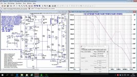
What would you say if looking the right side, the Loop Gain plot, is it CFA or VFA?
In isolation at one closed loop gain one can't tell from that. At the risk of opening a pointless argument I will state my criterion. In a CFA the CURRENT that drives the VAS flows in the feedback network, that is changing the scale (not the ratio) of the feedback resistors changes the open-loop transfer function of the amplifier.
What this demonstrates is that there is no agreed definition of CFA or VFA, everyone has their own definition. The real question is, who cares if it is, in someone's opinion, CFA or VFA? In every instance, that definition doesn't guarantee a blameless amplifier.
I reminds me a little of the arguments that raged when Quad brought out their current dumping amp...
It's what the amp does that matters. To use ostripper's definition, we need amps that are all EFA...
I reminds me a little of the arguments that raged when Quad brought out their current dumping amp...
It's what the amp does that matters. To use ostripper's definition, we need amps that are all EFA...
In isolation at one closed loop gain one can't tell from that. At the risk of opening a pointless argument I will state my criterion. In a CFA the CURRENT that drives the VAS flows in the feedback network, that is changing the scale (not the ratio) of the feedback resistors changes the open-loop transfer function of the amplifier.
Here I used simple probe an stepper Rf(CLG=Rf/R9+1) and it's clear that this is CFA.
Attachments
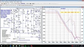
Here I used simple probe an stepper Rf(CLG=Rf/R9+1) and it's clear that this is CFA.
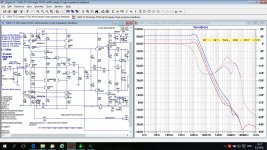
I said the scale not the ratio. In this example Rf || 22 Ohms which determines the OL transfer function (if CFA) hardly changes at all. Try 250,22 500,44 1000,88 or for that matter 10000 and 880 a VFA would not care, but there is peaking and other stuff going on that could obscure the point. As I said a pointless discussion.
This might indeed be CFA but this example is not a good test.
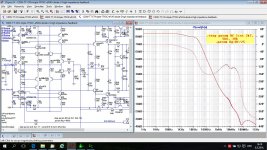
I think I simulated it correctly now.
P.S. Scott, probably this is pointless for you, but we, others, can learn something from it.
Attachments

Last edited:
P.S. Scott, probably this is pointless for you, but we, others, can learn something from it.
This is very much the point... learning the differences and nuances. Rather than scoring debating points.... I believe those here have adequately described the CFA in operation. There are also many books (forget marketing sheet info) on the subject which are quit clear in the differences. So there really is no argument about it. By doing the simulations it has become clearer and we can design either vfa or cfa or even a combo and know the trade-offs.
THx-RNMarsh
Last edited:
- Status
- Not open for further replies.
- Home
- Member Areas
- The Lounge
- John Curl's Blowtorch preamplifier part II