The floating approach works for the resistors too, although one doesn't get the benefits of high impedance. Still a PITA.How about using a dedicated statically shielded trafo winding to power the resistors? Possibly with a low-noise regulator or just power filter? That way there are also no offset currents from resistor/supply mismatch.
Eww, I know.
Well, I experimented this question of the linearity of feedback ratio in the audio bandwidth, long time ago and on a very subjective way (listening). I stay convinced that an amp sound better when open loop is flat at least up to 10KHz than the same amp with more open loop gain at low frequencies and lower FC.
And when slew rate allow *a lot* of margin.
Just my 'opinion'. It is like distortion numbers ;-)
Seems to work best that way to me also... except I use 40Khz for the -3db point OL.
What about you, JC, what do you find as the minimum OL bandwidth works best for you?
THx-RNMarsh
Now work out using a process 51 device what degeneration resistor you will need to get the necessary degeneration to get 25ma? And then try 40ma, which is what the SCP-1 uses. '-)
Last edited:
Some topoliges, like a diff amp driving another diff amp, if the second amp is biased high, at 25 mA or better, can provide full power OL bandwidth of better than 100 kHz, however with both first and second stage gain limiting.
H/K routinely does something like 80 kHz, working backwards, CL response is better than 250 kHz, and global NFB factor is 3:1, or 12 dB.
H/K routinely does something like 80 kHz, working backwards, CL response is better than 250 kHz, and global NFB factor is 3:1, or 12 dB.
> Harrison, Current Sources and Voltage References: A Design Reference for Electronics Engineers
Fully agree with you -- disappointing ......
Patrick
Fully agree with you -- disappointing ......
Patrick
Well, I experimented this question of the linearity of feedback ratio in the audio bandwidth, long time ago and on a very subjective way (listening). I stay convinced that an amp sound better when open loop is flat at least up to 10KHz than the same amp with more open loop gain at low frequencies and lower FC.
And when slew rate allow *a lot* of margin.
Just my 'opinion'. It is like distortion numbers ;-)
I'm with you, Christophe, but I wonder why stop at 10 kHz, why not go even higher?
At first glance, the somwhat obvious answer is that with higher gain, you can use more GNFB to reduce distortions, but please also conside this: if you reduce the open loop gain with local degeneration and let the VAS work with 20 mA or more, your inherent open loop distortion will also be reduced. Also, of your VAS is working into fixed loads like 10 Kohm or more, it will maintain its performance over a wider bandwidth than otherwise.
This also depends on what you take for your least permitted THD factor in conjunction with the GNFB you plan to use.
The only obscured downside to this approach is that since your GNFB factor is reduced, to get rid of crossober distortions you will likely have to use between 100 and 150 mA of bias per output device. This is no big deal to achieve, but in case of several outpout device pairs this can tax your heat sinks. Even if you have say 125 mA per device, at just 51V, with three device pairss you'll have a normal dissipation of 38 Watts with zero signal.
Payback is that you will also have less thermal shifting once the amp heats up.
big a$$ JFET
Not sure why I couldn't find it before, but now Mouser is carrying it!
InterFET Corp. Page Selector - IF3601 datasheet
They are expensive.
1: $19.16
10: $16.11
100: $14.83
250: $13.51
500: $12.63
1,000: $11.59
Not sure why I couldn't find it before, but now Mouser is carrying it!
InterFET Corp. Page Selector - IF3601 datasheet
They are expensive.
1: $19.16
10: $16.11
100: $14.83
250: $13.51
500: $12.63
1,000: $11.59
Last edited:
Yes, maybe, but if you achieve that, there is no way you'll pass a current through R5: if everything is perfectly floating, you'll just bias the transistors, no more: Kirchhoff's Current Law has no provision for compromises.In the case of the simplified pre-preamp shown by John in post 67475, if a floating current source with sufficient voltage compliance is used in place of R2 and R8, except for certain circuit impedances that are not perfectly complementary, the noise in the current source nulls at the output!
Of course we need to have outstanding isolation if we're still attempting to power things from the mains, or use batteries---and the latter are going to run down in a hurry with tens of milliamperes being pulled all the time.
Even if you magically surmount this hurdle, you will defeat the cascode action of the OP transistors
Nope. It works fine. Kirchoff is not being asked to compromise anything. The transistors still steer current in and out of R5, and the voltages are still anchored by Q2 and Q3 (note that the bias on their gates is not provided by the floating I source).Yes, maybe, but if you achieve that, there is no way you'll pass a current through R5: if everything is perfectly floating, you'll just bias the transistors, no more: Kirchhoff's Current Law has no provision for compromises.
Even if you magically surmount this hurdle, you will defeat the cascode action of the OP transistors
I'll clarify with a schematic in a bit.
Last edited:
Not sure why I couldn't find it before, but now Mouser is carrying it!
InterFET Corp. Page Selector - IF3601 datasheet
They are expensive.
1: $19.16
10: $16.11
100: $14.83
250: $13.51
500: $12.63
1,000: $11.59
That is new for Mouser to have them. They are tough to work with if you self bias them the noise performance is lost and the input capacitance is of course large. Fortunately we stocked up on Toshiba parts. Maybe someday they will get used for something.
> Maybe someday they will get used for something.
Something like this :
http://users.cosylab.com/~msekoranja/tmp/04447683.pdf
Patrick
Something like this :
http://users.cosylab.com/~msekoranja/tmp/04447683.pdf
Patrick
Yes, maybe, but if you achieve that, there is no way you'll pass a current through R5:
if everything is perfectly floating, you'll just bias the transistors, no more: Kirchhoff's Current Law has no
provision for compromises.
Think of the current source resistors as being open circuits for signal frequencies.
It's a cascode, but instead of connecting to the supply through a load resistor,
the signal path is folded to ground with an opposite polarity "upper" device.
Last edited:
Yeah that capacitance is huge. I fear I will be gone before a lot of my cherished parts are used for anything 🙁That is new for Mouser to have them. They are tough to work with if you self bias them the noise performance is lost and the input capacitance is of course large. Fortunately we stocked up on Toshiba parts. Maybe someday they will get used for something.
Another thing I did and mentioned somewhere was to stack a bunch of BF862 parts and interconnect them via a wire on the gate leads, which also serves as a heatsink. To my surprise a simple amplifier using the composite was not oscillating, even without any lumped inductance in the gate. And hey---it doesn't take up much extra board space---just height 😀
j111; 2SK170; IF3601 ...
I think you, guys, are on the wrong track. Those have way too high transconductance to be used as current sources in JC's folded cascode MC stage.
I think you, guys, are on the wrong track. Those have way too high transconductance to be used as current sources in JC's folded cascode MC stage.
Last edited:
Yeah I remember that paper. I would have done something about that input capacitance 🙂> Maybe someday they will get used for something.
Something like this :
http://users.cosylab.com/~msekoranja/tmp/04447683.pdf
Patrick
Don't think so, but let's wait for the clarification of bcarso. One thing is certain: without a return path from supplies (CCS?) to ground, there is no way to drive the output, you can just bias the transistors.Think of the current source resistors as being open circuits for signal frequencies.
It's a cascode, but instead of connecting to the supply through a load resistor,
the signal path is folded to ground with an opposite polarity "upper" device.
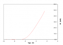
> = what degeneration resistor you will need to get the necessary degeneration to get 25ma? And then try 40ma .....
25mA Vgs = -3.9V; R degen = 156R; Yfs = 14mS
40mA Vgs = -2.9V; R degen = 72R; Yfs = 15mS
Patrick
.
25mA Vgs = -3.9V; R degen = 156R; Yfs = 14mS
40mA Vgs = -2.9V; R degen = 72R; Yfs = 15mS
Patrick
.
Attachments
Last edited:
- Status
- Not open for further replies.
- Home
- Member Areas
- The Lounge
- John Curl's Blowtorch preamplifier part II