Acknowledged for all but the Process 51, which is really not particularly high gm. But also realize that any I source is going to require higher-voltage rails to be competitive compared to the plain old 300 ohm resistors. You need to spend some volts and some power.j111; 2SK170; IF3601 ...
I think you, guys, are on the wrong track. Those have way too high transconductance to be used as current sources in JC's folded cascode MC stage.
It's interesting that before later parts appeared, process 51 (2N4391/2/3 etc.) was the device of choice for vidicon preamps. Then people started really shortening the channel to get higher transconductance-to-input-capacitance ratios, culminating today in parts like the BF862.
However, shorter channels also means higher output conductances, and these parts usually need to be cascoded for various reasons including lower composite output conductance and reduced lower device dissipation.
1- To try to stay satisfied of myself with the poor results I'm able to achieve, most of the time, in power amps. ;-)I'm with you, Christophe, but I wonder why stop at 10 kHz, why not go even higher?
2- I wonder if any H2 harmonic distortion at 20KHz can change so much the landscape.
See as well Bruno Putzeys' article in Linear Audio, "The F Word" for a discussion of the response of an amplifier with flattened open-loop gain versus OL gain that extends to low frequencies. He argues that the latter should not be a concern.
That article is online at linearaudio.net under Downloads. Scroll down a couple of pages.
Jan
Only one floating current source, which has to be powered from a sufficiently high voltage. But one end of the resulting composite circuit attaches to the Q3 Q4 junction, and the other end to the Q1 Q2 junction. Both ends thus are anchored to the voltages on each of those nodes, in turn determined by the cascode device gate voltages of around 7.5V for JC's simplified examples.Don't think so, but let's wait for the clarification of bcarso. One thing is certain: without a return path from supplies (CCS?) to ground, there is no way to drive the output, you can just bias the transistors.
> How about 160 ohms for 25ma, and 100 ohms for 40ma?
A hand-picked, high Idss J111 would come close to that.
Patrick
.
A hand-picked, high Idss J111 would come close to that.
Patrick
.
Attachments
Last edited:
Don't think so, but let's wait for the clarification of bcarso. One thing is certain: without a return path from supplies (CCS?) to ground, there is no way to drive the output, you can just bias the transistors.
During normal operation the load current doesn't flow through the current source resistors. Think of it like a bridged class A amp - the PSU current is constant even while the load is driven. The current flowing into ground from the input sources is the same current flowing into the output from the load.
Also, using just resistors and the isolated supply you may not get as much impedance as an active CCS, but what if you used a 300V winding (or voltage multiplier)? That's 300K for 1mA. Is that still not enough?
Last edited:
Can you post a schematic?Only one floating current source, which has to be powered from a sufficiently high voltage. But one end of the resulting composite circuit attaches to the Q3 Q4 junction, and the other end to the Q1 Q2 junction. Both ends thus are anchored to the voltages on each of those nodes, in turn determined by the cascode device gate voltages of around 7.5V for JC's simplified examples.
We are technical guys, and we thus know every detail counts: coincidentally, that's precisely where the devil generally hides...
To properly assess something, I need to have it in full details in front of my eyes, and a simple verbal description doesn't convey the information adequately.
Maybe I am just thick, but so far I do not see how it can work...
Something like JC's simplified sketch would do, we just need to check the fundamentals
Last edited:
Can you post a schematic, or even better a sim of what you think is happening?During normal operation the load current doesn't flow through the current source resistors. Think of it like a bridged class A amp - the PSU current is constant even while the load is driven. The current flowing into ground from the input sources is the same current flowing into the output from the load.
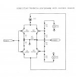
schematic
BTW this is pretty much what EUVL does with batteries (or floating supplies) and a matched set of JFETs, and has an article in Linear Audio about it as well as a thread in here. It works just fine, both in sim and in real life. It's not fully complementary like the Vendetta, however.Can you post a schematic, or even better a sim of what you think is happening?
Attachments
> .... and has an article in Linear Audio ...
Here is the link :
http://linearaudionet.solide-ict.nl/sites/linearaudio.net/files/didden-la -vol2euvl.pdf
It was really a JFET version of the Leach Common-Base MC Preamp but used for DAC IV conversion instead.
Moving Coil Cartridge Head Amps
So we might as well just go back to the Leach and replace the BJTs with JFETs.
😉
Patrick
Where is the current into R7 coming from?BTW this is pretty much what EUVL does with batteries (or floating supplies) and a matched set of JFETs, and has an article in Linear Audio about it as well as a thread in here. It works just fine, both in sim and in real life. It's not fully complementary like the Vendetta, however.
I only see the input, or Vs1, or Vs2 as possible sources, but that would be problematic
Last edited:
I will show a practical example, but remember that the power for Is1 is from a floating supply of whatever voltage compliance we need. Although looking at the schematic for such a current generator we typically identify one terminal as the high-Z node and the rest of it low-Z, in this case as it is floating both ends are high Z.Where is the current into R7 coming from?
I only see the input, or Vs1, or Vs2 as possible sources, but that would be problematic
EUVL has one version, Sen, of his I-V converters (which can be described as current conveyors with resistive output loads) which has an upper JFET as a common-gate config and a lower device as a current sink. Then a floating voltage source ties from the upper device drain to the lower device source, and there is a divider across that sets the output voltage to about half of the floating supply voltage. That center tap gets loaded with a resistor, which determines the conversion gain, amps in to volts out. The overall polarity is non-inverting. If you consider the lower device and the battery as functioning like Is1 on my schematic, you can see how it works.
> .... and has an article in Linear Audio ...
Here is the link :
http://linearaudionet.solide-ict.nl/sites/linearaudio.net/files/didden-la -vol2euvl.pdf
It was really a JFET version of the Leach Common-Base MC Preamp but used for DAC IV conversion instead.
Moving Coil Cartridge Head Amps 1999.
So we might as well just go back to the Leach and replace the BJTs with JFETs.
😉
Patrick
I designed a common base circuit for a MC pre-preamp as well but it was direct coupled and no coupling caps were needed. Published in TAA (1/1982). Recently E.Borbely used my same topology in Linear Audio but where mine was all bjt, his is all jFET.
THx-RNMarsh
Last edited:
Something closer to realizable
So we know the top of the battery sits at about 7.5V, and we know the drain of Q5 sits at about -7.5V. If Q5 and R8 need another 15V to work well, the battery voltage needs to be 30V so that the gate of Q5 is at -22.5V. As noted the impedance of the I source thus realized could be raised appreciably with a cascoded JFET, but we'll need still higher battery voltage.
Brad
I will show a practical example, but remember that the power for Is1 is from a floating supply of whatever voltage compliance we need. Although looking at the schematic for such a current generator we typically identify one terminal as the high-Z node and the rest of it low-Z, in this case as it is floating both ends are high Z.
EUVL has one version, Sen, of his I-V converters (which can be described as current conveyors with resistive output loads) which has an upper JFET as a common-gate config and a lower device as a current sink. Then a floating voltage source ties from the upper device drain to the lower device source, and there is a divider across that sets the output voltage to about half of the floating supply voltage. That center tap gets loaded with a resistor, which determines the conversion gain, amps in to volts out. The overall polarity is non-inverting. If you consider the lower device and the battery as functioning like Is1 on my schematic, you can see how it works.
So we know the top of the battery sits at about 7.5V, and we know the drain of Q5 sits at about -7.5V. If Q5 and R8 need another 15V to work well, the battery voltage needs to be 30V so that the gate of Q5 is at -22.5V. As noted the impedance of the I source thus realized could be raised appreciably with a cascoded JFET, but we'll need still higher battery voltage.
Brad
Attachments
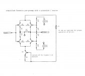
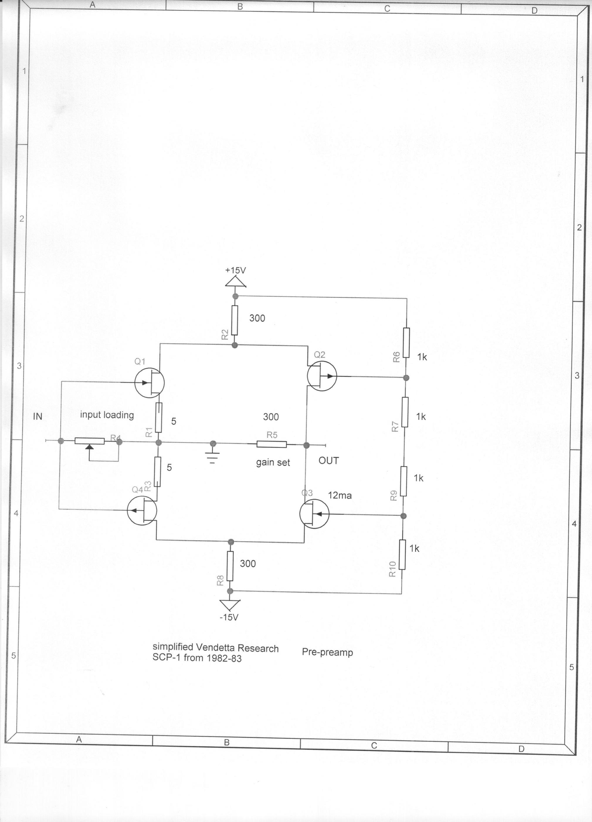
Elvee, the second two Jfets are cascodes, with their drains at the output. So the output current comes from the input Jfets, not from the resistors.
Here is what I'm thinking.
Isnt this a 'folded' cascode... complimentary version. gain set by R7/300 Ohm....making cascode also like transconductance stage.
-RNM
and the noise
Put an additional I gen across the floating I source and observe the output voltage on the 300 ohm load. As mentioned earlier, owing to the imbalance of capacitances and to some extent conductances, the nulling is not perfect but dramatically better (lower) than the noise gain to the output from independent I sources.
Put an additional I gen across the floating I source and observe the output voltage on the 300 ohm load. As mentioned earlier, owing to the imbalance of capacitances and to some extent conductances, the nulling is not perfect but dramatically better (lower) than the noise gain to the output from independent I sources.
Yep. It's JC's simplified circuit, with just the 300 ohm pullup and pulldown resistors replaced with a single current source.Isnt this a 'folded' cascode... complimentary version. gain set by R7/300 Ohm....making cascode also like transconductance stage.
-RNM
- Status
- Not open for further replies.
- Home
- Member Areas
- The Lounge
- John Curl's Blowtorch preamplifier part II