Back emf is mostly caused by a motional mechanism: the shorting ring makes the magnetic field ~infinitely stiff regarding perturbations caused by the coil.
I therefore doesn't shunt anything useful, quite the opposite in fact.
I suppose this is because it's not physically coupled to the voicecoil? And at frequencies where the cone inertia prevented movement between the coil and shorting ring, the ring would behave as if it was physically coupled to the coil, and act as a shorted turn on the coil, shorting out the back-EMF?
If so, then I wonder at what frequencies this occurs. If the current drive impedance necessary to make a large improvement is 330R or so, and shorting ring impedance is close to zero at a very high frequency, it may still be low enough at low frequencies to thwart current drive.
I've made an electromechanical model of a hard drive motor in the past, which was quite fun. I think I might be able to make a nonlinear electromechanical speaker model with some things I've learned since then.
Circa 1930 Voigt and Lowther were doing this.
Thornsten was also mentioning Eckmiller http://www.diyaudio.com/forums/lounge/200865-sound-quality-vs-measurements-482.html#post3002630
Control of Amplifier Source Resistance
by Charles A. Wilkins, Journal of the Audio Engineering Society, January 1956
https://www.aikenamps.com/images/Documents/sourcer.pdf
George
Yes, there it is!
Note the resistor bridge used to allow the pot to sweep both positive and negative output impedance's.
When I worked at Grommes in the 70’s, they had a couple tube amplifiers that had a stacked WW pot wired to get that same adjustment. It made sense back then as T&S parameters weren’t used and so if you put a driver ina box that was a bit too large or too small to get a nice lf corner, you could adjust the Q electrically. Normally, the electromagnetic damping (Qe) is vastly greater than mechanical losses and such. To get a negative impedance, you add some of the current signal to the input signal.
Best,
Tom
Plus the paper that SY mentioned:
Transconductance Power Amplifier Systems for Current-Driven Loudspeakers
P. G. L. MILLS and M. O, J. HAWKSFORD
http://citeseerx.ist.psu.edu/viewdoc/download?doi=10.1.1.211.4368&rep=rep1&type=pdf
George
Transconductance Power Amplifier Systems for Current-Driven Loudspeakers
P. G. L. MILLS and M. O, J. HAWKSFORD
http://citeseerx.ist.psu.edu/viewdoc/download?doi=10.1.1.211.4368&rep=rep1&type=pdf
George
Last edited:
Great literature set, thank you George 🙂
I haven’t seen a group buy for printer ink refills 😀
JAES Volume 3 Issue 3 pp. 132-142; July 1955
Thanks Dimitri. Who was the author?
Yes, there it is!
Note the resistor bridge used to allow the pot to sweep both positive and negative output impedance's.
It would be an omission not to link to Rod Elliot’s page for a modern touch 🙂
Variable Amplifier Impedance
(I have built it with LM1875 and it works OK) http://www.diyaudio.com/forums/multi-way/91466-impedance-current-source-amplification-4.html#post1077117
George
Nelson, when you were playing with current drive, did you do any distortion measurements or did you stick to frequency response?
I didn't dwell on distortion, as I was trying to stick to the simple DIY thing,
but I have observed that voltage source vs current source gives some
differences in distortion, dependent on the source of the distortion in the
driver.
Back EMF of the speaker into a voltage source does give some
"degeneration" which lowers distortion - by this I mean that velocity
distortion invites more current from the amplifier. This velocity distortion
can be the result of mechanical non-linearity or magnetic field non-linearity.
This effect is fairly small, however.
My few comparisons have left me with the impression that current-source
drive is not much of a panacea for harmonic and IM distortion given the
same acoustic output.
😎
I haven’t seen a group buy for printer ink refills 😀
Thanks Dimitri. Who was the author?
It would be an omission not to link to Rod Elliot’s page for a modern touch 🙂
Variable Amplifier Impedance
(I have built it with LM1875 and it works OK) http://www.diyaudio.com/forums/multi-way/91466-impedance-current-source-amplification-4.html#post1077117
George
What i think was the first commercial version;
Philips Motional Feedback (MFB) loudspeaker
I attended one of Malcolm's presentations on the current amplifier back then.
What i think was the first commercial version;
Possibly, but I recall Infinity playing with motion feedback about that time.
😎
What i think was the first commercial version;
Philips Motional Feedback (MFB) loudspeaker
I attended one of Malcolm's presentations on the current amplifier back then.
That's really interesting. I take it the device in the center of the cone is an accelerometer?
The IRS that I played with used a strain gauge.
Looking back at Hawksford's 1984 article, I see that his measured results
of lower distortion for current-source driving were with motional feedback.
Personally, I have also done this sort of thing with microphones, secondary
voice coils, and current-sensed feedback. They all work as long as you don't
expect miracles.
😎
I haven’t seen a group buy for printer ink refills 😀
That's one lesson we could take from the Chinese, their big printers have pumps and gallon jugs of ink. I was at a shop printing copies of scrolls for tourists.
Drivers which are planar types and ribbons, also Heil, etc are low Z and very low L and magnetic structure which is very different. And, there is the electro-static.... all seem to minimize the problems of conventional drivers and amplifier interaction.
Wouldn't they have lowered amp interaction (back emf etc). What do we get for current distortion with those types of drivers?
THx-RNMarsh
You're correct, magnetic planers has much less dynamic issues, inductance is much lower and spring/mass resonances are close to eliminated. Drawbacks are size, placement and poor efficiency, just look back at the Apogee's even to modern days standards they where magnificent loudspeakers.
At Raidho we use a magnetic planar tweeter, for the same reasons. No mass related resonances incredible low mowing mass 30-50 times less than any done. A very pure concept that we have polished over the last 15 years
We also build our own dynamic drivers, here we work hard to reduce VC inductance, we're currently at app 30% of what we had in the previous version. of the driver. Actually there's a lot that can be done to reduce notional resonances in speaker designs, this is a great priority for us
No. It was Matsushita. 1961 (Luxman, Panasonic)
Panasonic SA-30 - National SA-30 - Panasonic EASB-8M2
But it was Philips the first (and only?) that sold MFB speaker driver units (8”, 10”, 12”) for anyone to build a speaker system
I take it the device in the center of the cone is an accelerometer?
It is a piezoelectric element.
I remember years ago when repairing a set of RH 532, the suspended element was making problems because the elastic suspension had age hardened.
George
Attachments

Last edited:
Nice to see discussion of the myriads of little details that matter, for getting speakers to better behave - what a shame that something similar doesn't occur for the electronics side of things, 😛 ...
The interesting thing about dynamic speakers, in spite of this avalanche of weaknesses that have been noted, is that they are still capable of producing intense, convincing sound - Dan's experience with the Jand's amp tells the story, here.
My experiences tell me that huge amounts of money, brainpower and effort will be thrown at getting the acoustic transducer to perform brilliantly - and guess what? It still won't do the job: people will listen and say, yes, it's all very nice and I'm sure technically it's pretty spiffy - but you know, I don't actually enjoy listening to it, it's not doing much for me ...
And why? Because there are still problems in the reproduction chain, as a system - it still doesn't "work" ...
Sorry to bug people about this, but it is important to get the message across: even a very cheap, mediocre speaker driver can be driven well enough, with a clean electronics signal to the point where the speaker becomes invisible - that is, no matter how closely you listen to the transducer, and how loud it is, within the limits of the system capabilities, you can't "hear" the driver working - the illusion of the recorded material overrides any distortion that the driver also adds to the mix. In most systems the treble driver fails this test worst of all - but when a setup works this well it does create a remarkable illusion - making the actual transducer itself brilliantly "correct" will certainly help, but it definitely is not a guarantee for good sound.
No. It was Matsushita. 1961 (Luxman, Panasonic)
Panasonic SA-30 - National SA-30 - Panasonic EASB-8M2
But it was Philips the first (and only?) that sold MFB speaker driver units (8”, 10”, 12”) for anyone to build a speaker system
It is a piezoelectric element.
I remember years ago when repairing a set of RH 532, the suspended element was making problems because the elastic suspension had age hardened.
George
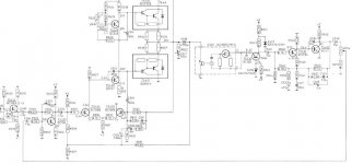
Yeah that wasn't it, this was he one or one like it back then.
This uses current feedback, not an accelerometer and a variation of a much older dc motor control technique for improving speed regulation.
Motional feed back amplifier - Electronic Circuits and Diagram-Electronics Projects and Design
And like i said the company i worked fo in the early 70's had several amlpifiers that had this kind of feedback. I still have one of these out in the garage "somewhere";
http://www.jogis-roehrenbude.de/Leserbriefe/Roessler-Amp/Grommes_260A.gif
http://www.jogis-roehrenbude.de/Leserbriefe/Roessler-Amp/Grommes_260A.gif
... the company i worked fo in the early 70's had several amlpifiers that had this kind of feedback.
How would you characterize the benefits vs. disadvantages of this type of design?
Me too John although I am more on the transducer side than amplifier side now days.
There is a paradox which no one caught in my earlier post. The linearity of the motor system is the primary distortion source for a woofer. The distorted waveform “shows up” because the motor’s force sensitivity changes with position instead of being a constant. This might be likened to the transfer function curve of many other real world devices.
My point was that in the back emf Voltage , on the other side of the Rdc, one has a measure of the driver velocity which includes the distortion and can be used as a negative feed back signal.
In he Servodrive subwoofers we used to make in the 80’s and 90’s I fiddled with PWM amps which were the norm for servomotors back then and found that they were neither a current or voltage amplifier but were a duty cycle controller. In making one from scratch, one needed to derive the output voltage and current, filter it from rail to rail hash into an analogue signal for feedback.
If one has lowered the output impedance below zero, the motion related distortion is reduced but the response is tipped as if Qe were VERY VERY small. If one has Current drive one has the response shape as if Qe were very large and usually increased distortion.
The reason as seen in the earlier rotary motor analogy, a motor driven by a current source has no speed regulation, it exerts a fixed amouth of torque from stopped to safe max speed. A motor driven by a Voltage source through a small resistor will slow down a little when loaded down but the amount of load is partially reflected in the increased current drawn under load. A motor driven with a perfect negative impedance equal to the motor Rdc when loaded will not slow at all and the load is entirely reflected in the increased current. With a loudspeaker, you have a simple DC motor, it's just driven with an AC signal. Where the motor oscillated proportionally back and forth, the voice coil moves proportionally in and out.
The best solution I think is to have the least non-linearity, fewest things to fix possible even in very large scale sound.
Best,
Tom Danley
Danley Sound Labs
i was talking with john about this, back in 2012, 2013.
How the problems are nearly unsolved in these 'systems', never mind remaining unsolved in the amplifiers.
I spent years (Ok, two decades) trying to figure out what to do. I hit upon a series of solutions and have placed them in various 'standard' amplifier designs. About 6-7 of them so far.
In each case, the amplifier can be taken to the point of nearly (or actually, I'm serious) catching on fire, and it sounds as effortless and as clean and dynamic, as it did when driven in it's most perfect comfort zone in the perfect complimentary system.
ie zero signs of strain, nothing at all. All you hear is the onset of square waves when it becomes obvious. Other than that...nothing. Just absolute unremitting balls.
This is in pure solid state, with high to mid feedback systems, which, in my experience are notorious for sounding hard and go into break up when driven hard.
Last edited:
- Status
- Not open for further replies.
- Home
- Member Areas
- The Lounge
- John Curl's Blowtorch preamplifier part II