Thanks, but I have to be stoic about lost royalty income. Mark Levinson cut me off back in 1976, on royalties for this line stage. That is why I published it in TAA in 1977. It is public domain now, as far as royalties are concerned.
Is there a JC copy which uses fet follower OPS ??
THx_RNMarsh
It doesnt have to be a simple follower (high distortion) but just low output Z and can drive longer cable C without affecting its performance into low z loads (600 Ohms).
Speaker IM tests---- can the two IM signals (from a L + R spkr) combine in air to create additional IM products -- at 90dB spl at mic/listener location?
Or, maybe one tone 12KHz from one (L) speaker and another tone 13Khz from the other speaker (R) will also show products when combined in the air?
THx-RNMarsh
Last edited:
It is very good to see those measurements from Pavel, but if I was in the same situation I would then do more extensive testing, to understand where the contributing factors are:
Capture the electronics behaviour with the test signals into a dummy load
... with the electronics hooked to the speakers under test, at the amplifier terminals, for a range of power out
... with the electronics hooked to the speakers under test, at the speaker terminals, for a range of power out
... with mic in front of speaker with range of power fed to them
... with mic in front of speaker, with a fixed power; and when speaker drivers are dead cold, when warmed up and stabilised, and directly after they have been heavily thrashed for a while
... with the electronics hooked up to the speakers, and record at the speaker driver terminals
... drivers removed from cabinet, disconnected from crossover, mounted in a stable, isolated environment, and driven directly; record with mic
That way, I might have a good chance of fully comprehending what's going on ...
Last edited:
It's worth doing so, as an exercise; from my experiments it can be done to any level provided the feedback mechanism is well enough engineered, and one is prepared to have devices running at high dissipation levels, ensuring that sufficient current drive is always available.Of course, there are better amps that don't have xover distortion. I try to make them when I can, and you do too, PMA, but most here would not bother to, and would say that it is not worth the time and cost to make amps of this quality. That is the fundamental argument debated here.
But an amp doesn't have to have brilliant technical performance to achieve subjectively high quality sound - obviously good technical, good subjective is ideal, but all combinations of good and bad are possible.
Speaker IM tests---- can the two IM signals (from a L + R spkr) combine in air to create additional IM products -- at 90dB spl at mic/listener location?
THx-RNMarsh
The SPL required is rather large, remember like many low level non-linearities there is a power law relationship. There is a wealth of literature on this.
Last edited:
Or, maybe one tone 12KHz from one (L) speaker and another tone 13Khz from the other speaker (R) will also show products when combined in the air?
Hard to see how such a recording would occur without very close miking, and how the result would be different in the real event with 2 suitably loud sources. I mean the intermodulation must occur there too? Unless we're talking about music that is assembled totally in the recording domain.
the problem has been addressed, "solved" to the extent of making at least voice quality audio appear out of thin air from ultrasonic nonlinear mixing in the air
several times in fact in the 1990's Sound from ultrasound - Wikipedia, the free encyclopedia
you can buy them: Audio Spotlight - Add sound and preserve the quiet.
lots more at AES, Czerwinski is one researcher on air nonlinearity distortion in normal audio band transducers at Rock Concert speaker array levels: AES E-Library Propagation Distortion in Sound Systems: Can We Avoid It?
not really an issue with musicians, human powered instruments - much higher SPL is needed for air nonlinearity to give audible IMD
What I would like to know is what mechanism creates any significant amount of higher order harmonics from a loudspeaker, itself?
Hi John. Here:
https://www.klippel.de/fileadmin/kl...linearities?Causes,Parameters,Symptoms_06.pdf
https://www.klippel.de/fileadmin/kl...s/Large_signal_performance_of_tweeters_05.pdf
https://www.klippel.de/know-how/literature/papers.html
... with the electronics hooked to the speakers under test, at the speaker terminals, for a range of power out
... with the electronics hooked up to the speakers, and record at the speaker driver terminals
...
If the distortion is measured and compared at amp terminals and then (using just lamp cord pair) measured at speaker terminals with 15-20 feet of wire, I have seen quite large distortion numbers. This is why, I brought up (another forum) the motional feedback signals getting back into the amp; OPS isolation from IPS/VAS et al.
THx-RNMarsh
not an issue with high feedback amps, audio frequencies - amp output Z at the feedback takeoff can be microOhms
yes can see the internal nodes move as feedback does it thing if the load demands complex or even nonlinear current
but >1/2 century old Bode/Classical Frequency Domain Sensitivity analysis really does cover this as long as the usual linear operation caveats apply
the amp, output stage, PS, ect all have to be able to supply the worst case load demand for feedback to steer it to low error
what significance you want to give to added load isolating Inductor, cable Z also dropping V with nonlinear current load is for the user to decide - and take steps to mitigate if it really is a problem
short, fat cables, Kelvin Sensing, individual amp per speaker driver...
Scott, please see microphone input (preamp, open input) noise floor itself and the same with phantom-powered ECM8000 connected. IMO it is the capsule noise + noise of electronics integrated in the ECM body.
looks like a flat noise source with a 1 pole lowpass at 20 Hertz or so.
Gerhard.
It is very good to see those measurements from Pavel, but if I was in the same situation I would then do more extensive testing, to understand where the contributing factors are:
Capture the electronics behaviour with the test signals into a dummy load
... with the electronics hooked to the speakers under test, at the amplifier terminals, for a range of power out
... with the electronics hooked to the speakers under test, at the speaker terminals, for a range of power out
... with mic in front of speaker with range of power fed to them
... with mic in front of speaker, with a fixed power; and when speaker drivers are dead cold, when warmed up and stabilised, and directly after they have been heavily thrashed for a while
... with the electronics hooked up to the speakers, and record at the speaker driver terminals
... drivers removed from cabinet, disconnected from crossover, mounted in a stable, isolated environment, and driven directly; record with mic
That way, I might have a good chance of fully comprehending what's going on ...
Frank, I have been doing similar tests for several years. Few years ago I started with class AB amplifiers with reasonably low distortion, but no phantastic numbers. Speaker distortion results were close to indistinguishable with 2 different AB amplifiers.
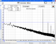
This last set was done with pure class A amplifier. It is tested with R, dummy load and speaker. I can measure distortion of this amplifier only with a notch filter method, the result is attached. When I try direct method, the amplifier distortion is lower than that of the measuring chain.
Sorry I am not going to provide you with tens plots, it is useless. Theories from a land of phantasy would always appear even if thousands of measurements were posted.
...feedback
nonsense.
And this setup is an extremely low distortion preamp + class A unity gain stage with no global feedback.
Attachments
yes can see the internal nodes move as feedback does it thing if the load demands complex or even nonlinear current
...
I brought this up in other forum where circuit designs are being created in SIM (and some built from the SIM), a generator applied to output could easily see it back at the VAS stage. The solution was greater isolation from the speaker via a triple BJT OPS or FET OPS etc.
There are some very finely tuned designs being created here at DIY-land.
BTW -- it was B.Thornton who showed me this test decades ago and ask me if I knew why the distortion at the speaker end was higher.... he demo'ed this affect in his hotel room at an early CES convention in LVegas...... he used a high gnfb VFB amp for the test.
THx-RNMarsh
Last edited:
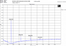
These 2 measurements are made at tweeter axis, same amplifier output voltage. Microphone position is 40cm and 140cm from tweeter. One can see 11dB difference in SPL. If the microphone added SPL related distortion, we would see higher distortion numbers for 40cm distance (higher SPL). Opposite is true, 40cm distortion numbers are lower (pls see top left corner of both plots), maybe more reflecftions in 150cm distance, or midrange contribution.
Klippel - I have seen down to 5th in some of his measurements.
Klippel - I have seen down to 5th in some of his measurements.
Attachments

Pavel, thanks for the "feedback" - sorry, 😀.Sorry I am not going to provide you with tens plots, it is useless. Theories from a land of phantasy would always appear even if thousands of measurements were posted..
It is very pleasing that you went to these efforts - I appreciate your exercise of varying the mic distance from the driver, to confirm that it was not subject to SPL related distortion.
Unfortunately, we are still no closer to understanding, in terms of measuring, what the behaviours are that are sufficiently subjectively disturbing to inhibit the sound reproduction from being convincing. Hopefully, at some stage I might be in a position to try similar sorts of experiments, from my perspective on things - but, not at the moment.
Frank, I have found my measurements at speaker terminals with speaker connected ...
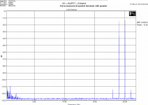
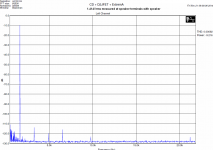
Please take into account that there is an influence of the soundcard used to the result. Even with this influence, we can see that the distortion at speaker terminals with speaker connected is negligible (at least with amplifiers that I use) and absolutely negligible to what we see with acoustical measurement.
I agree with you that we are not much closer to explanation of sound differences, but at least I wanted to stop blaming all on amplifier crossover distortion etc. IMO harmonic distortion is NOT an explanation.
Attachments
Nice, thanks ... of course, you are using an excellent amp for doing these tests, 😉 - I do wonder though, how the average over the counter unit would travel here ... 🙂.
I have shown voltage at speaker terminals. I assume that if I measured current flowing into the speaker, the situation might be different. Now the task, to measure speaker current with high resolution and precision.
The speaker current should reflect speaker non-linearities in the spectrum.
The speaker current should reflect speaker non-linearities in the spectrum.
- Status
- Not open for further replies.
- Home
- Member Areas
- The Lounge
- John Curl's Blowtorch preamplifier part II