Adding two paralleled diodes upside down between the center transformer wire and ground ?
Correct! Now who did it first?
Pavel,
Would you care to start the list of all the advantages?
ES
It was unclear to me also, but is now making sense. I'd be interested if there is more to the story.
You'll want to consider primary and secondary common and differential mode filtering, interwinding shielding, and snubbing (especially the secondaries). A broad-based approach to making quiet supplies is more effective than just focusing on one or two aspects and trying to rhodium plate them.
SY,
Do you care to elaborate on your additions to the list?
I am not big fan of inter-winding shielding as it does increase line coupling to the shield which creates the problem of where do you return those currents. I prefer dual or split bobbin designs and isolating the core from the chassis. (See a Citation 12 for an example.)
ES
J.C. ? He did everything first. 😉Correct! Now who did it first?
I wonder why R core are so rare and expensive, that is the best solution and easy to manufacture.I am not big fan of inter-winding shielding as it does increase line coupling to the shield which creates the problem of where do you return those currents. I prefer dual or split bobbin designs and isolating the core from the chassis. (See a Citation 12 for an example.)
Last edited:
I am not big fan of inter-winding shielding as it does increase line coupling to the shield which creates the problem of where do you return those currents.
Chassis. It's not a problem, it's a feature. See, for example, how I did this in my phono and line preamp designs which are extremely quiet and don't have issues with line noise pickup at any levels above ridiculous.
There's an excellent and thorough treatment of these issues (as well as the others I mentioned which don't seem to concern John) in "Valve Amplifiers" 4th ed. You'll also see an excellent survey of proper ways to do snubbing in an upcoming Linear Audio (I think the next issue).
Agreed, split bobbin is a great way to go. That's even more important in tube amps, which have some unique ways for noise to creep in.
Borbely ..... 😛
Borberly showed amazing ability to spot an improvement, redo it with his style and present it. But the first place I ever saw it was.... well I won't feed John's ego!
Chassis. It's not a problem, it's a feature. See, for example, how I did this in my phono and line preamp designs which are extremely quiet and don't have issues with line noise pickup at any levels above ridiculous.
There's an excellent and thorough treatment of these issues (as well as the others I mentioned which don't seem to concern John) in "Valve Amplifiers" 4th ed. You'll also see an excellent survey of proper ways to do snubbing in an upcoming Linear Audio (I think the next issue).
Agreed, split bobbin is a great way to go. That's even more important in tube amps, which have some unique ways for noise to creep in.
But SY you know I go for ridiculous levels!
Bipolar junction transistors are much more susceptible to the problem than red hots. The consumer electronics industry is going to double insulated and plastic chassis. So the current design trend is to use different shielding techniques.
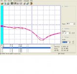
Now Rick Miller mentioned using higher voltage diodes as they have less capacitance than lower voltage types. What was not mention is the difference in switch off voltage between the two, attached is a shot showing the difference between a 1N4004 rated at 400 PIV and 1 amp versus a 2.5 amp 1000 volt generic replacement diode.
Very little difference. It is getting harder to find soft recovery diodes and from my measurements commodity diodes are getting much quieter.
So what else do you want to expand on?
Attachments
Last edited:
Although the forward drop is considerably higher, SiC is quite impressive. I wish they made some small ones. Ditto GaN.But SY you know I go for ridiculous levels!
Bipolar junction transistors are much more susceptible to the problem than red hots. The consumer electronics industry is going to double insulated and plastic chassis. So the current design trend is to use different shielding techniques.
Now Rick Miller mentioned using higher voltage diodes as they have less capacitance than lower voltage types. What was not mention is the difference in switch off voltage between the two, attached is a shot showing the difference between a 1N4004 rated at 400 PIV and 1 amp versus a 2.5 amp 1000 volt generic replacement diode.
Very little difference. It is getting harder to find soft recovery diodes and from my measurements commodity diodes are getting much quieter.
So what else do you want to expand on?
Pease once pointed out that many (he may have said "all") silicon schottkies had a "parasitic" P-N junction diode along for the ride, which spoils the fine-structure in reverse recovery.
So what else do you want to expand on?
Nothing, really. These are solved problems, and people who want to read about them have plenty of resources; I'm sure your review will be interesting and educational.
Diode switching can be handled with proper snubbing and layout. Having soft recovery makes that easier, and these days, soft recovery diodes are dead cheap. Circuit design and layout for noise rejection is even more important, but doesn't make good stories, apparently.
Correct! Now who did it first?
According to the patent 4,555,751 (Nov 1985) it was Koga et al
I’ve traced patents with back to back diodes for noise reduction as far back as 1936
In idiosyncratics this must mean “I appreciate your input”Duh! '-)
George
According to the patent 4,555,751 (Nov 1985) it was Koga et al
I’ve traced patents with back to back diodes for noise reduction as far back as 1936
George
Very interesting patent. They have the center tap inverse parallel diodes, but for a different reason! They want to keep the signal from going back into the transformer.
Yes diodes have been used as noise clippers for a very long time. (And you know that is not the same thing.)
Last edited:
Very interesting patent. They have the center tap inverse parallel diodes, but for a different reason! They want to keep the signal from going back into the transformer.
The center tap hosts a lot of traffic due to static and dynamic unbalanced currents. The back to back diodes reduces the nastiness of it.
With dual –and bifilar- split secondaries, each feeding it’s own bridge, working conditions become more civilized.
Yes diodes have been used as noise clippers for a very long time. (And you know that is not the same thing.)
I wish I was certain that it’s not the same thing.
Strange. On this very topic, there was a paragraph in US patent 3,166,639 that caught my eye. I quote:
“For reasons not fully understood, the non-linear characteristic of the silicon rectifiers in the threshold region contributes to this noise reducing characteristic. Thus, the non-linear forward resistance of the rectifiers causes a distortion of the noise waveforms which appears to augment in a favorable manner the basic clipping action provided by the rectifier’s unilateral characteristics. For these and other reasons, silicon diodes or semiconductors of comparable characteristics are preferred.”
I don’t know if this was a misconception of the time (1965) but I am scratching my head realizing that I have never seen a back to back diode implemented with tubes.
Does anyone know anything on this?
I am not big fan of inter-winding shielding as it does increase line coupling to the shield which creates the problem of where do you return those currents.
ES
I think that the proper think to do is to return these currents at the noise originator’s site.
True, we read conflicting implementations in the literature, as the writers can not be certain as to which ground point has the least impedance (this is also important). This is to be determined by the builder of the circuit.
I prefer dual or split bobbin designs
I agree. For power transformers and less noise feedthrough, the less capacitive coupling btn prim and sec, the better. (*)
Additionally, increasing the primary inductance (more turns, lower Volts/turn) works for a smoother sinusoidal waveform.
George
(*) Inevitably this increases the leakage inductance (spreading of the magnetic field)
I would give provisional first credit to Koga. I did it independently, a few years later. Still later, I went with dual bridges, with the Vendetta Research SCP-2A as a first effort in about 1989.
I would give provisional first credit to Koga. I did it independently, a few years later. Still later, I went with dual bridges, with the Vendetta Research SCP-2A as a first effort in about 1989.
Thank you Mr. Curl
Can you give us YOUR reasoning for implementing center tap back to back diodes and YOUR reasoning for implementing dual rectifying bridges?
George
I don't think that I can add to what Ed Simon has already offered, except that the dual bridge removes one potential ground loop. I saw this in the late 1980's when I upgraded the SCP-2 to the SCP-2A
Splitt bobbin transformers, low C diodes, RC across the sec of the transformer, and an RC stage after the bridge to reduce the harmonics and RFI that is left. I like to keep the RF as low as possible before the DC voltage goes into the first PN junction in the regulator and starts mixing to produce IM products.
Well, some of us find that close attention to these relatively unused techniques do wonders for audio quality. It avoids the necessary use of batteries, which is a viable alternative to a good power supply. Unfortunately, batteries are even more expensive with medium current designs and wear out relatively quickly. That is why we try so hard to make the best power supplies that we can manage. Works for me (and my reputation).
As I found on the first batterry powered JC MC preamp... 1.5v batteries have a too high source Z and it just gets worse (higher) as they age and are drained. They also do not have a great transient energy - rise time. A very large cap across a battery is needed. So transformer c.t./grounding is one issue but then we get others. Regulated stable low Z vs freq is overall better sounding than batteries. So you are back to square one re. rect/xfmr/ct grnd. -Thx-RNMarsh
Last edited:
- Status
- Not open for further replies.
- Home
- Member Areas
- The Lounge
- John Curl's Blowtorch preamplifier part II