depends on the batteries. I have several battery packs with impedance less than 12.5mOhms and capable of 140A
They all start out fine but dont end up that way in use over time.depends on the batteries. I have several battery packs with impedance less than 12.5mOhms and capable of 140A
What kind of batteries are-you refering-to ? Acid, cadmium or lithium/ion ? (I'm more thinking to a preamplifier than a power amp, of course)They all start out fine but dont end up that way in use over time.
They all start out fine but dont end up that way in use over time.
yeah look i'm not sure you have used anything like what i'm talking about. with proper care in undervoltage protection and the use of chargers designed for them, quality LiFePO4 last for literally thousands of full cycles at much higher discharge rates than what we are speaking of here. i've been using the ones I have here daily for well over 18months and they still perform pretty much as the day I bought them. they are 2300mah. there are also higher capacity ones if need be, but for a preamp I could see them not needing charging for a week (24hrs of use at 100mA for example) so 1000 weeks is ~20years and they should still be sitting at roughly 90% capacity of new
Last edited:
Don't forget Kelvin caps!
SY
What kind of animal is this ? (I searched but didn't find any explanation)
George
What ? You don't know ?SY
What kind of animal is this ? (I searched but didn't find any explanation)
(i asked myself the same question)
SY
What kind of animal is this ? (I searched but didn't find any explanation)
George
Probably these:
http://www.nist.gov/calibrations/upload/tn1024.pdf
4 terminal = Kelvin connections.
Kelvin caps, I used them once, long ago.
However, Richard is correct. We both know from EXPERIENCE what a pain in the --- that batteries can be. We have both designed with batteries, they 'float' but give little more than that compared to a 1'st Class AC-DC power supply.
However, Richard is correct. We both know from EXPERIENCE what a pain in the --- that batteries can be. We have both designed with batteries, they 'float' but give little more than that compared to a 1'st Class AC-DC power supply.
4 leaded caps I presume, with kelvin connection
Exactly. Suppression Devices sells them at pretty reasonable cost. The advantages in power supplies are small but measurable.
No more the case, as noticed by qusp. Modern batteries are cheap, reliable, long lasting and low impedance.We both know from EXPERIENCE what a pain in the --- that batteries can be.
You could easily build a preamp with two sets of batteries inside, able to work 24/24 (one set used during 24H, while an other set is charging quietly in 4 hours.). And keep your audio stages totally isolated from AC.
Last edited:
Oh, i use 3 leaded caps in my amp. Nice to know their names 🙂4 leaded caps I presume, with kelvin connection
Splitt bobbin transformers, low C diodes, RC across the sec of the transformer, and an RC stage after the bridge to reduce the harmonics and RFI that is left. I like to keep the RF as low as possible before the DC voltage goes into the first PN junction in the regulator and starts mixing to produce IM products.
Rick,
One of the tricks to the RC filter across the secondary is that you can use a parallel RC instead of series. If you can stand a bit of heat the R can also increase the transformers regulation.
George,
We mostly agree. Of course when you look where to sink ground currents that is a non-trivial issue. I have on my desk this week a sound system specification calling for 1" copper buss bars in every rack. A sure fire method to guarantee hum!
As to the Koga patent. I used to have to fix lots of amplifiers. What was clear on the Japanese commodity amplifiers of the 70's and early 80's, if the outputs are blown it was from a shorted speaker line. If the drivers were blown it was from an open speaker line. As the driver transistors ran at a slightly higher voltage if the power supply voltage went up they would fail. The mechanism was because the outputs were swinging an inductive load that unloaded had no where to dump their energy. I think this patent addresses this issue. Of course the language used is not quite clear.
Of course the issue became unimportant as transistors got higher SOA's.
As to the noise clipper patent, I have an old Ham book that shows both neon lamps and dual diodes used as clippers! (Transformers required.) The tube technique use a step up transformer to the first clipper then an inverting and step up transformer to the second diode.
Dick et al.
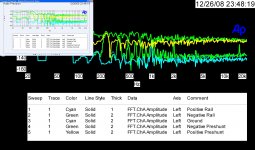
The noise floor of a battery can be calculated from the internal resistance which rises with age and use. (Of course you knew that.) In an AC powered supply you usually use regulators that are feedback based and can lower the effective resistance of the power supply. Of course you can also regulate a battery supply. I do use 12V 4AH lead acid batteries that are followed by active filtering circuitry in my most sensitive measuring gizmos.
Attached is the FFT of the power supply rails in a preamp before and after a pair of shunt regulators. There also is a trace of the input shorted. (It processed a bit strange but you can still read it so I am too lazy to redo it!)
Attachments
Last edited:
What voltage. The capacitance of a diode is voltage dependent.Has anyone thought of the C of the diodes? I have been trying out some high voltage (1KV) diodes with low C, with good results. I measured 18pf of C with these diodes. Less C for less noise passed thru when the doide is off.
Yup...good one.Not to mention that the magnetic field radiated from the transformer will increase and will "look" much more nastier if the core approaches saturation.
So it might not only be a mechanical noise problem if any susceptible receiver loops are waiting.
As the material starts to saturate, it starts to lose control over field containment. 1.5 tesla is pretty much a good upper limit.
A 4 wire cap gets rid of the mutual coupling of the lead wires.SY
What kind of animal is this ? (I searched but didn't find any explanation)
George
jn
Re Kelvin Caps
Thank you guys.
http://www.diyaudio.com/forums/tubes-valves/223432-morgan-jones-kapacitors-2.html#post3239780
Intuitively 😀 I’ve done an approximation of this a couple of times. I haven’t done any measurements.
Talking about caps, what works for me is a cap directly over the + and – terminals of op.amps (I use 1uf MKT) or on discrete circuits (up to 10uF MKT). It provides local circulation of locally generated unbalanced currents.
George
The Kelvin connection caps take that one step further and essentially eliminate cross-coupling of noise/ripple and interstage coupling through the power supply. I've tried the Suppression Devices polyprops and they work as advertised. Reasonably priced, as well. SD do an excellent job of getting tight windings and low ESR/ESL. No datasheet, but Valve Amplifiers 4th edition has detailed analysis and measurements showing the advantages.
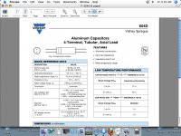
Link to the datasheet for the electrolytics that John mentions:
http://www.vishay.com/docs/42040/604d.pdf
Link to the datasheet for the electrolytics that John mentions:
http://www.vishay.com/docs/42040/604d.pdf
I have on my desk this week a sound system specification calling for 1" copper buss bars in every rack. A sure fire method to guarantee hum!
How? This is supposed to reduce hum (copper bars of racks to be all wired in parallel to safety ground )
As the driver transistors ran at a slightly higher voltage if the power supply voltage went up they would fail. The mechanism was because the outputs were swinging an inductive load that unloaded had no where to dump their energy
Troubleshooting tip appreciated.
I guess a large cap there would act as a fast dump container.
So this is how a back to back diode was made with tubes! ThanksAs to the noise clipper patent, I have an old Ham book that shows both neon lamps and dual diodes used as clippers! (Transformers required.) The tube technique use a step up transformer to the first clipper then an inverting and step up transformer to the second diode.
Any idea about the beneficial nonlinearity of the silicon diodes that the patent talks about?
George
How? This is supposed to reduce hum (copper bars of racks to be all wired in parallel to safety ground )
So this is how a back to back diode was made with tubes! Thanks
Any idea about the beneficial nonlinearity of the silicon diodes that the patent talks about?
George
When you have three wire AC power cords there is always some small current induced on the safety ground. This may be due to coupling in the run to the source or in this country the neutral and safety ground are tied at the building entrance. So when you connect equipment to the safety ground and then tie the chassis to another ground any voltage imbalance on the neutral goes back to the safety ground tie, back to your gear's chassis and then into a second ground. So adding a second ground path insures a current will flow! Unfortunately the consultants don't understand this and can't follow the explanation, so they keep on doing it. Just to make it more interesting the thicker or less resistance in the second ground the lower the hum level. So the devil really knows how to tempt folks. (For the hard of understanding, just draw it out and you will see you have placed your safety ground in parallel with the neutral, so any voltage drop on the neutral is now on your chassis. The thicker wiring just makes that voltage closer to the same for all of the chassis.)
They didn't need a back diode with tubes. The first stage would clip the positive peaks using a diode to a voltage source. They they would invert the signal with a transformer and do the same again. That way they clipped both positive and negative peaks. Very clever folks!
No clue about the added benefits of silicon diodes!
ES
Last edited:
When you have three wire AC power cords there is always some small current induced on the safety ground. This may be due to coupling in the run to the source or in this country the neutral and safety ground are tied at the building entrance. So when you connect equipment to the safety ground and then tie the chassis to another ground any voltage imbalance on the neutral goes back to the safety ground tie, back to your gear's chassis and then into a second ground. So adding a second ground path insures a current will flow! Unfortunately the consultants don't understand this and can't follow the explanation, so they keep on doing it. Just to make it more interesting the thicker or less resistance in the second ground the lower the hum level. So the devil really knows how to tempt folks. (For the hard of understanding, just draw it out and you will see you have placed your safety ground in parallel with the neutral, so any voltage drop on the neutral is now on your chassis. The thicker wiring just makes that voltage closer to the same for all of the chassis.)
ES
There wasnt a saefty issue about multiple ac power grounds... as far as the national electrical code (NEC) and operation of equipment, like refridg, stoves, and toasters, and lamps. or even a TV. BUT, with cpu's and other more sensitive equipment now on line, the latest electrical codes DO employ a single point ground... for new homes. That leaves millions of homes still with multiple grounds - and ground loops. Such as grounding CATV at entrance and telephone at its entrance and power at its panel/entrance to building. However, Hum is still not the reason for a single point ground (at the power panel entrance to the building) rather it is for lightning protection, fire/damage. A high current transient (lightning ground/earth strike) can cause a large voltage difference between seperated ground points, thus causing high current to flow thru various connected equipment -- fire and smoke is the result. However, it is also good for your music systems and interconnected computer system etc. if you can tied all the grounds together. -Thx RNMarsh
Last edited:
- Status
- Not open for further replies.
- Home
- Member Areas
- The Lounge
- John Curl's Blowtorch preamplifier part II