IMO the only cheap technology that touched the chicks of hi-end was LM1875 🙂D but no 😀 )
Interesting - I pulled up the schematic and it shows the input LTP degen resistors are unusually high at 3k3. Compare that to the LM3886 family of devices where they reduce those resistors to around 1k. I rather suspect though that for high end sound in chipamps, the TDA2003A would beat it as this part dispenses with the LTP entirely 😉 TDA2003A is also ridiculously cheap 😀
Interesting - I pulled up the schematic
…
TDA2003A is also ridiculously cheap 😀
Abraxalito
I didn’t mean to be technical (I would agree with you though)
The 47 Labs product was a -pun intended I guess – experiment, which the embarrassed “hi-end” establishment (construct) swallowed due to bearing an oriental haze / designer’s name and a insane price.
The LM1875 itself was a junk to them before that and regarded as such even now without such “proper” dressing. It’s not what you serve. It is how you serve it.
This is a universal truth for everything but the very essentials for surviving.
George
What is being said here. Is is that somebody, somewhere, faked a hi end item with a cheap IC inside?
For the record, the FIRST TIME that I saw such fakery was in the late '70's from a FRENCH company who had a very fancy case, with a 'joystick' volume control, yet used cheap parts like uA741 type IC's inside.
Of course, there will be people who fake things, and others who are gullible. But they will not last with the test of time. That is an important difference.
For example, the Marantz 9 power amp is still a reference standard, spoken about even today, by those who have listened to it.
What is being said here. Is is that somebody, somewhere, faked a hi end item with a cheap IC inside?
No. Nothing like that.
And it was LM3875. Sorry
Attachment assembled from here
Mick Feuerbacher Audio Projects
6moons audio reviews: 47 Laboratory Model 4706 GainCard
George
Attachments
No. Nothing like that.
George
Nothing like that at all, how do you "fake" a high end product. The reviewers and customers are happy. Read Steve Rochlin's hubris, he even mentions the Ongaku a "real" high end product.
I love the web site repleat with bad grammar and mis-spellings and associations with traditional Zen art. The designer is also an artist with a separate site you can visit.
Last edited:
George,
I actually use Gain Clones! I combine them with a few dozen 600/600 transformers and use them for press feed boxes. So virtually anyone in this country who has listened to any of a half dozen NFL teams press conferences has heard one, in at least part of the chain.
The commercial product almost everyone else uses is here: A-24/2ML & A-24/2ML/B Audio Press Feed | Opamp Labs Inc.
I think they have improved it since the last time I looked. Then it used 2N3055 vintage output transistors and designs.
However I think Gain Clones are an excellent first project for many folks.
ES
In a major way, the PROOF is in the listening. Unfortunately, for the strictly logical types, SOME electronics (and speakers) work better than they measure. Why this is so, I do not know. But you will never fool me, either way, as to what something sounds like, so long as I know what source I am listening to. This is where I differ from my critics.
My critics want me to participate in a listening test where different sources are presented and I have to match the same sound from the different sources, randomly presented, double blind. BUT the musical material is constantly changing, and I could easily make a mistake. I found this so, 1/3 century ago, and I wrote up my opinion about it in 'TAA' back in 1979. However give me an A, or a B, and ask me which I prefer, that I can usually do. That is the heart of my listening feedback.
My critics want me to participate in a listening test where different sources are presented and I have to match the same sound from the different sources, randomly presented, double blind. BUT the musical material is constantly changing, and I could easily make a mistake. I found this so, 1/3 century ago, and I wrote up my opinion about it in 'TAA' back in 1979. However give me an A, or a B, and ask me which I prefer, that I can usually do. That is the heart of my listening feedback.
There is another factor that is important in the high cost of limited production hi end components. That is: The materials and the care in fabrication that goes with the design.
IF it costs money and time, then the costs go up. This is where mass production makes the majority of products that we use and 'enjoy' affordable. I personally can't afford many of the products that I design, yet I still design them.
IF and WHEN people make a truly successful audio product that is so perfect, yet easily affordable, then everybody will use it, and the rest of us will retire.
But you will never fool me, either way, as to what something sounds like, so long as I know what source I am listening to.
This is the truest thing you've ever said.
Could somebody post a schematic of the power supply and rectifier circuit with all the components placed, no values necessary at this point. So that would be a split transformer with two sets of rectifiers and shunting of the diodes and everything else you have wanted. I would like to see the entire circuit drawn as imagined. That would include the shunting of the secondary windings and all the things at once. RF filters and the entire kitchen sink..........
SY is just trying to 'tease' me. He apparently thinks that I am deluding myself, and that my efforts in promoting hi end audio are a waste of time. I believe that he is sincere in his opinion. However, I stick to my opinions, and hope to go forward.
Sorry, this is what's crippling the audio industry: premium quality components, used within the "right" circuit configurations, is the only thing that will pass mustard, is the type of thinking. Well, I've listened to some pretty dreadful "hifi" over the last 25 years, virtually unlistenable to. And these systems reeked of all the "correct" methods being used -- as always, it's the intelligence of the designers and manufacturing companies that determine whether the end result is worthy of anything ...The LM1(3?)875 itself was a junk to them before that and regarded as such even now without such “proper” dressing. It’s not what you serve. It is how you serve it.
This is a universal truth for everything but the very essentials for surviving.
George
I'm happy to report that lowly gainclones can easily "annihilate" very pretentious equipment if correctly sorted out; yes, they may have weaknesses, but in one fell swoop they eliminate a whole bundle of problems that more "designed" circuits happily include just about every time ...
Frank
Could somebody post a schematic of the power supply and rectifier circuit with all the components placed, no values necessary at this point. So that would be a split transformer with two sets of rectifiers and shunting of the diodes and everything else you have wanted. I would like to see the entire circuit drawn as imagined. That would include the shunting of the secondary windings and all the things at once. RF filters and the entire kitchen sink..........
We just might get there. But there should be a few more quizzes and discussion to make sure the design decisions are understood. For example why does John put his coil filter after the rectifier?
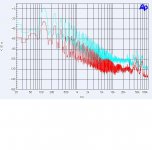
But here is today and tomorrows quiz. Attached is the FFT Spectrum of a power supply's output voltage. It consists of a 24 VAC center tapped transformer with just two diodes providing a positive voltage to the filter capacitor. Two different capacitors are shown. One is 470uF the other 10,000uF. The question is what is the load that makes so much noise? (0 db= 1 V RMS)
Attachments
Last edited:
George,
Ed
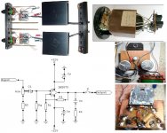
It may be my poor English or my poorer communication skills. It’s not about Gaincard or Gainclone.(*)
It’s about the Hi-End amusing arena.
The “experiment” shoots many Hi-End taboos (and equally many of local’s worries) with a single shot:
An IC power Op.Amp. for mass consumer markets.
Schematic is a direct copy of manuf. data sheet application (non-inverting configuration mind you)
Phenolic single sided board. No ground planes, no input guards (and solder flux not cleaned off)
5% carbon resistors (even at the stepped attenuator)
Rf is 1/8W
Electrolytic cap at input.
Electrolytics may be BG or garden variety (can’t tell. Plastic cover removed)
Plain wires for inter-wiring.
Single power-signal ground
To add insult to the injury, no one from that area bothered to mention the C core/ split bobbin transformer, the only –justifiable-costly component on the complex (they all praised the thick chassis though).
Mind the small electrolytics (<100uF) after the rectifiers and the four wires connecting the PSU with the amplifier.
George
(*) I’ve supported IC power op.amp merits here many years ago and I have built many.
I have read that Dave Wilson of Wilson Audio gave a demo at the CES one year and only had his speakers in view, all the electronics were behind a screen. He told everyone that the source was a tube based CD player. After the demo, and everyone told hm how good his speakers sounded, he pulled back the screen to show that the source was an Apple MP3 player. He said that this was to show that the speakers were the most important part of a system. Do you think that this is because he sells speakers? :^)
In your list of amplifier features you forgot to mention:gpapag said:The “experiment” shoots many Hi-End taboos (and equally many of local’s worries) with a single shot:
A carefully crafted story
A 'designer' from the mystical East
A suitably high price
These are what distinguish some 'high end' from ordinary audio.
PS augmented, of course, by the usual high-quality investigative audio journalism which ruthlessly exposes reality in the service of their readers
Last edited:
I thought that I shouldn’t repeat them for a third time 😀In your list of amplifier features you forgot to mention:
http://www.diyaudio.com/forums/anal...ch-preamplifier-part-ii-3224.html#post3311360
http://www.diyaudio.com/forums/anal...ch-preamplifier-part-ii-3225.html#post3311905
George
But here is today and tomorrows quiz. Attached is the FFT Spectrum of a power supply's output voltage. It consists of a 24 VAC center tapped transformer with just two diodes providing a positive voltage to the filter capacitor. Two different capacitors are shown. One is 470uF the other 10,000uF. The question is what is the load that makes so much noise? (0 db= 1 V RMS)
If I was taught something from my endevours here
http://www.diyaudio.com/forums/power-supplies/184068-psu-rc-multistage-filtering.html
is that it’s not the load that makes “so much noise”. But I’ll wait for your proof.🙂
George
- Status
- Not open for further replies.
- Home
- Member Areas
- The Lounge
- John Curl's Blowtorch preamplifier part II