Yes, that is a time-honored technique that I've used as well, despite the extra diode drops.
I guess I was just puzzled that you introduced (or re-introduced) the subject at this point. But as you say, the concept of a thread topic is long gone.
ThorstenL, (Kuei Yang Wang) advocated this in the long past.
There is also a dedicated thread. Pay attention to Fred Dickmann contribution (post #38)
http://www.diyaudio.com/forums/chip-amps/12162-2-rectifier-bridges-why-4.html#post143874
Of course, apart from more balanced loading of the separated secondary windings, it all boils down to better defined return paths (hello jneutron ! )
George
Last edited:
Thanks for the input, Ed, Brad, and others. Yes, I use the dual bridge in the CTC Blowtorch.
Advantages of 2 bridges have been known for a long, long, long time.
Pavel,
Would you care to start the list of all the advantages?
ES
Much better rejection of interference voltages, you can easily measure it and compare to center-tapped bridge. You are capable enough to do it yourself, Ed. Ground contamination of center-tapped bridge is MUCH higher.
Much better rejection of interference voltages, you can easily measure it and compare to center-tapped bridge. You are capable enough to do it yourself, Ed. Ground contamination of center-tapped bridge is MUCH higher.
You mean like this?
Attachments

yes. My sediments, exactly 🙂
Are you a stone, or you did mean sentiments, Ryan? 🙂
being able to use the better performance positive linear regulators for both polarities is a handy split sec/dual bridge feature
but in a preamp avoiding most of the single bridge-CT common impedance noise isn't that hard with intelligent layout, routing, choice of gnd points - in power amps the currents are a little large for doing it right with just pcb trace - but still can be largely attenuated compared to naive implementations
but treating it as a pro level audio amp design secret when the issue is shown in Self, Cordell books is a little behind the times - either nih syndrome or once again propping up a strawman version of what "conventional enigeering" knows, even modestly well read interested audio amp designers should have seen
Last edited:
who cares about ancient history, exact path to best practice, it all has to come form somewhere - and some local "audio" designers seem to be reluctant to credit EE as having more sophistication, many sub fields, think they don't have to look in any other specialty for design principles, insights
but now its in audio power amplifier design "textbooks", hard to deny that == "what conventional (audio) engineering knows"
but now its in audio power amplifier design "textbooks", hard to deny that == "what conventional (audio) engineering knows"
As we know:
1. It is impossible
2. It is possible but not important
3. We invented it. '-)
You left out 1. "It's in every engineering textbook, but sneering is fun."
As we know:
1. It is impossible
2. It is possible but not important
3. We invented it. '-)
You come back with that line even when exact dated prior art is shown to you.
being able to use the better performance positive linear regulators for both polarities is a handy split sec/dual bridge feature
but in a preamp avoiding most of the single bridge-CT common impedance noise isn't that hard with intelligent layout, routing, choice of gnd points - in power amps the currents are a little large for doing it right with just pcb trace - but still can be largely attenuated compared to naive implementations
but treating it as a pro level audio amp design secret when the issue is shown in Self, Cordell books is a little behind the times - either nih syndrome or once again propping up a strawman version of what "conventional enigeering" knows, even modestly well read interested audio amp designers should have seen
No, we are not talking about ground resistance issues.
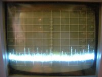
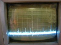
The noise under discussion is coming from the AC line. When you use the dual bridges, the diodes only pass current and noise during a small part of the cycle. That is shown in the last two spectrums I posted. It is about 10 db less noise that gets through. That is not corrected by layout.
Where is this feature covered in Self or Cordell? I have a nice collection of engineering books. I haven't seen that in any of them. Which ones address the issue?
Do you want to expand on why using a half bridge from a center tapped transformer as shown earlier has DC issues?
Maybe SY or Scott could tell us the technique to reduce the line noise on a center tapped transformer and where it first appears?
Last edited:
I don't see how "the diodes only pass current and noise during a small part of the cycle" is markedly different with CT - diodes still only conduct during a small part of the cycle
any differing sec Rseries (possibly partially compensated by the xfmr designer unbalancing the turns) only modifies relative conduction times on the margins
charging pulse frequency can also beat against load current - modifying ripple, CT current - I'd guess a much larger effect in typical amps
care to tell how the modify the sim in http://www.diyaudio.com/forums/head...eadphone-amp-linear-audio-32.html#post3071120 to highlight the effect you're so concerned with?
and an estimate of how bad your amp's psrr has to be to hear the effect in music (related Q: can you hear a Sousa March at -60 dB?)
Attachments
I don't see how "the diodes only pass current and noise during a small part of the cycle" is markedly different with CT - diodes still only conduct during a small part of the cycle
any differing sec Rseries (possibly partially compensated by the xfmr designer unbalancing the turns) only modifies relative conduction times on the margins
charging pulse frequency can also beat against load current - modifying ripple, CT current - I'd guess a much larger effect in typical amps
care to tell how the modify the sim in http://www.diyaudio.com/forums/head...eadphone-amp-linear-audio-32.html#post3071120 to highlight the effect you're so concerned with?
and an estimate of how bad your amp's psrr has to be to hear the effect in music (related Q: can you hear a Sousa March at -60 dB?)
All the noise from the AC line that is coupled through the transformer goes straight into your ground plane. It is there for 100% of the time. With the diodes in the bridge they only conduct 30% of the time so you have 10 db less noise.
Look at the actual measurements!
For a first level sim as you show you would have to model a noise source and the layout inductances and capacitances.
Why don't you build an amplifier with 60 db of S/N ratio and let me know how it sounds?
The S/N reference you site always keeps the noise 60 db below the program. Now all you need to do is modulate the noise to stay 60 db down as your program level changes to get the same effect.
It was unclear to me also, but is now making sense. I'd be interested if there is more to the story.All the noise from the AC line that is coupled through the transformer goes straight into your ground plane. It is there for 100% of the time. With the diodes in the bridge they only conduct 30% of the time so you have 10 db less noise.
Look at the actual measurements!
I still don't understand what you're getting at - pri-sec are isolated, have some interwinding coupling C
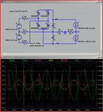
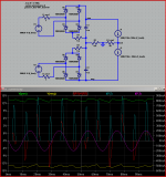
modified the above linked sim, separated sec - conduction angle looks pretty similar - summing the current with proper wiring, hierarchical gnd still works as far as I can see...
please do tell what more is needed to see your point - and its relative magnitude
in my house I only practically "have" to keep the noise 60 dB below reproduced audio output down to ~70-80 dB SPL - do you listen in a anechoic chamber - to minutes of silence?
but I like as evidence of technical competence to do much better than -100 dB re fs for power line artiacts
Attachments
Last edited:
Are you a stone, or you did mean sentiments, Ryan? 🙂
It's an old joke from W.C.Fields. Maybe too old.
missed edit time trying(failing) to clean duplicate post...
I still don't understand what you're getting at - pri-sec are isolated, have some interwinding coupling C, do you mean you omitted the line side EMI filter?
line noise still capacitively couples 100% of the time through the bridge's diodes, and you have 2x bridges, EI split bobbin can have low pri-sec C - same order as bridge diode C -so not much savings is possible
the conduction angle comment has me totally confused
modified the above linked sim, separated sec - conduction angle looks pretty similar - summing the current with proper wiring, hierarchical gnd still works as far as I can see...
please do tell what more is needed to see your point - and its relative magnitude
in my house I only practically "have" to keep the noise 60 dB below reproduced audio output down to ~70-80 dB SPL - do you listen in a anechoic chamber - to minutes of silence?
but I like as evidence of technical competence to do much better than -100 dB re fs for power line artiacts
Attachments

Last edited:
- Status
- Not open for further replies.
- Home
- Member Areas
- The Lounge
- John Curl's Blowtorch preamplifier part II