Actually the 100 Ohm source impedance is enshrined in that place where all useless and progress defying standards are: the EU IEC standards. There are also maximum output standards and sensitivity standards and everything needed to make a bureaucrats heart glow.
What would we do without them? Aside from perishing from the earth of course 😀
Actually the 100 Ohm source impedance is enshrined in that place where all useless and progress defying standards are: the EU IEC standards. There are also maximum output standards and sensitivity standards and everything needed to make a bureaucrats heart glow.
Meanwhile, such headphones are not considered as high end. However, kilovolt going by wires to human heads to drive electrostatics sounds quite different than 100 Ohm standard resistors...
Hi,
Most Op-Amp's do not have much more quiescent current in the output stage. I probably would look for even lower Beta Transistors (Video ones), but these seem to rare now. What I used to use in the 80's was Mini TO-3 case (forgot what they call them now) video one, beta around 30...
If you must have more current you can always add a resistor across the transistor BE connection. This depends on the Op-Amp you use.
I have not found the need to add these resistors back when I used this circuit to drive line output transformers and headphone outputs in mixing desks using these freaky east-german open collector output "Audio" Op-Amp's. There I used (obviously) a PNP Transistor and "ring of 2 CCS" (317's not around)... So shutting down halve the Output was no issue.
As said, the same trick works for NE5534, where Pin 5 is open collector output.
Ciao T
That's about 1 ma (order of magnitude) base current in the output transistor. Is that enough to turn off one of the opamps transistors reliably?
Most Op-Amp's do not have much more quiescent current in the output stage. I probably would look for even lower Beta Transistors (Video ones), but these seem to rare now. What I used to use in the 80's was Mini TO-3 case (forgot what they call them now) video one, beta around 30...
If you must have more current you can always add a resistor across the transistor BE connection. This depends on the Op-Amp you use.
I have not found the need to add these resistors back when I used this circuit to drive line output transformers and headphone outputs in mixing desks using these freaky east-german open collector output "Audio" Op-Amp's. There I used (obviously) a PNP Transistor and "ring of 2 CCS" (317's not around)... So shutting down halve the Output was no issue.
As said, the same trick works for NE5534, where Pin 5 is open collector output.
Ciao T
Well, that's all there is, Folks! You are on your own. (with the HP amp)
Personally my HP amp is direct coupled tube drive into Stax Electrostatics. Beats an IC anytime!
Personally my HP amp is direct coupled tube drive into Stax Electrostatics. Beats an IC anytime!
I loaned the work Stax amp (also the tube version) and matching headphones for about a year in Japan. They are wonderful, especially the midrange and top end. Someone clearly took a lot of time to get that set-up to sound good.
If these integrated amps which have been brought up are able to dissipate the extra power, you can force the output stage into class A (for a given headphone impedance) by resistor or ccs to one rail.
Quick'n dirty solution to avoid the "starved output stage" problem.
Quick'n dirty solution to avoid the "starved output stage" problem.
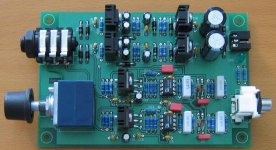
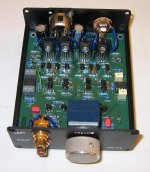
This is another one, a 2 box design prototype. Discrete sounds better.
What did you do differently on he discrete design?
What about this: http://www.ti.com/lit/ds/symlink/tpa6120a2.pdf 100 MHz and .0002% THD? The 7th harmonic isn't much less than the 2nd, but they are both in the -110 dB range with no load. Almost no external parts. The plots below I just measured.
Good to see TI reads the audio forums. 🙂 I can't believe the tilt in figure 23 is real. Microphone preamps??? I guess it does everything.
What about this: http://www.ti.com/lit/ds/symlink/tpa6120a2.pdf 100 MHz and .0002% THD? The 7th harmonic isn't much less than the 2nd, but they are both in the -110 dB range with no load. Almost no external parts. The plots below I just measured.[snip].
Demian or Scott: this and similar chips have a thermal pad back that is supposed to be soldered to a heaksink-plane on the PCB.
Is there any way that a diy-er at home without an IR reflow oven can mount such a chip in the recommended way?
jan
While not directed to me Jan I would like to answer your question. There is a convient way to do so. On the PCB add a larger plated through hole (or several) in the center of the thermal pad. These are necessary to connect the pad thermally to an inner layer or the adjacent side copper as seen on page 24. The larger pads allow solder to more easily flow through and create the thermal conduit needed to reflow the solder from the opposite side. To assemble add some solder to the center pad on the component side of the board. Since there is about 0.006 inch space between the component bottom of the component and the thermal pad, this solder added forms a mound to bridge the gap. The next step requires a bit of ambidextrous work. Place the package over he solder mound and reflow the solder from the bottom through the plated holes. Make sure the component is aligned with the other pads and remove the heat. Now solder the part pins being careful not to add too much solder. Not simple but doable.
Dave
Dave
Hi,
For prototyping I simply tin the pad (also below the PCB, don't put solder-resist there for prototypes) and IC's pad (very quickly on the IC) and then position the IC as well as possible and then heat the pad from the bottom until the solder flows. A toothpick can help keep the IC in place.
This probably does not follow the suggested heat profile and all and given that I use non ROHS solder for this cannot be sold, but I have yet to kill a chip that way.
Using a Toasteroven with suitable manual heat control is another option...
Ciao T
Demian or Scott: this and similar chips have a thermal pad back that is supposed to be soldered to a heaksink-plane on the PCB.
Is there any way that a diy-er at home without an IR reflow oven can mount such a chip in the recommended way?
For prototyping I simply tin the pad (also below the PCB, don't put solder-resist there for prototypes) and IC's pad (very quickly on the IC) and then position the IC as well as possible and then heat the pad from the bottom until the solder flows. A toothpick can help keep the IC in place.
This probably does not follow the suggested heat profile and all and given that I use non ROHS solder for this cannot be sold, but I have yet to kill a chip that way.
Using a Toasteroven with suitable manual heat control is another option...
Ciao T
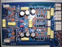
What's with all the input relays? Loading? (Although one looks like it might be gain).
Thanks,
Chris
Thanks,
Chris
- Status
- Not open for further replies.
- Home
- Member Areas
- The Lounge
- John Curl's Blowtorch preamplifier part II