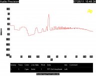
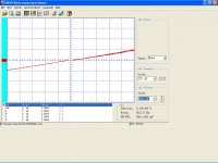
I promised a look at the FFT of my test setup. Shown is the output of my preamp being fed through the attenuator and the capacitor as shown in the second image.
I did change to an external Jensen isolation transformer and turned down the gain to 100 db or so by changing the middle stage feedback resistor to 10K
Also attached is a closeup of the zero crossing of the electrolytic capacitor.
I did change to an external Jensen isolation transformer and turned down the gain to 100 db or so by changing the middle stage feedback resistor to 10K
Also attached is a closeup of the zero crossing of the electrolytic capacitor.
Attachments
Last edited:
I promised a look at the FFT of my test setup. Shown is the output of my preamp being fed through tha attenuator and the capacitor as shown in the second image.
I did change to an external Jensen isolation transformer and turned down the gain to 100 db or so by changing the middle stage feedback resistor to 10K
Also attached is a closeup of the zero crossing of the electrolytic capacitor.
Try constant current in the cap through zero.
John
Try constant current in the cap through zero.
John
I think we both know what to expect. This is more typical of how a coupling capacitor is used. After I finish running things as it is set up I may try it, as surprises are interesting.
I have a few other interesting plots, but they didn't transfer as I though they would, so next play session I will have to see if they are still in the scope's memory.
Ah, but current slew rate is a confounder..I think we both know what to expect. This is more typical of how a coupling capacitor is used.
Lets see just how starved the dielectric can get...shall we?
It's always fun to see Faraday at work..in the strangest of ways.
Cheers, John
Ah, but current slew rate is a confounder..
Lets see just how starved the dielectric can get...shall we?
It's always fun to see Faraday at work..in the strangest of ways.
Cheers, John
Remember Faraday had to stay in the servant's quarters!
For those trying to understand the FFT most of the noise floor is from the 100 ohm source resistor!
Scott,
Try a ruler on the screen for a comparison.
ES
Makes me seasick. 😀
Sophisticated analog computing circa 100BC. The story of this is amazing, only one found by total luck.
The wheels of Greek astronomical science
The wheels of Greek astronomical science
Hi John,
Is that Sprague replacement cap your doing? If it helps at all, I've been taking digital pictures of "as found" work ever since I got a digital camera. They can really save your bacon, even from a small interruption. I wish I had a digital camera way back when I began my service career! Th internet would have been fantastic as well!
Good luck on your restoration there.
-Chris
Yes, but not often. I think they were used so replacements could be made quickly as a guess. The fuse clips do make a nice heat sink though ...notice those cartridge rectifiers?? I had never seen anything like that before..neat..
Is that Sprague replacement cap your doing? If it helps at all, I've been taking digital pictures of "as found" work ever since I got a digital camera. They can really save your bacon, even from a small interruption. I wish I had a digital camera way back when I began my service career! Th internet would have been fantastic as well!
Good luck on your restoration there.
-Chris
Here's a cool analog computer on Jim Williams' living room wall:
Jim Williams Tek 465B Fix v3 - YouTube
Jim Williams Tek 465B Fix v3 - YouTube
Hi Ed,
Now is it just a measurement/screen artefact of am seeing a "dead zone"?
Ciao T
Also attached is a closeup of the zero crossing of the electrolytic capacitor.
Now is it just a measurement/screen artefact of am seeing a "dead zone"?
Ciao T
Sophisticated analog computing circa 100BC. The story of this is amazing, only one found by total luck.
The wheels of Greek astronomical science
Wow! That is an incredible story- at least two millennia ahead of Babbage!
🙂
I promised a look at the FFT of my test setup. Shown is the output of my preamp being fed through the attenuator and the capacitor as shown in the second image.
I did change to an external Jensen isolation transformer and turned down the gain to 100 db or so by changing the middle stage feedback resistor to 10K
Also attached is a closeup of the zero crossing of the electrolytic capacitor.
Now, explain how this capacitor knows it is crossing through zero? It will need to be biased, so at each point on the curve, there will be a voltage across the cap.
Must be the machine.
vac
Now, explain how this capacitor knows it is crossing through zero? It will need to be biased, so at each point on the curve, there will be a voltage across the cap.
Must be the machine.
vac
There is no power at 0 volts.
I just had an interesting test result.
I was getting lots of noise at the bottom limit of my AP System 2 FFT tests. So I decided to try running the AP from my isolated AC power source. It cleaned up the noise and gave me about 8 db better noise levels.
So I decided to capture the same test with isolated power vs straight from the tap. Ran the isolated test, saved it and changed the AC cord. I rebooted the software and ran the same test again. The noise did not come back! So did the wiping action on the IEC power inlet make the difference or did something else change?
So if you are getting a bit of noise try cleaning the AC connections and see if that makes a difference!
ES
Indeed, isolated mains power and cleaning the power connectors affect noise level - both in measurements and in listening. In listening, some other things, like different power cords, have audible differences.
Hi,
My test setup uses multiple isolation transformers with electrostatic screens, so all grounds can be floated safely. On top of that I use cables with very low screen impedance for measuring and if need be additional straps to connect the chassis together.
Just plugging everything together into one extension and using RG-59 increases noise appreciably, DESPITE the AP2 being designed to be resilient to these effects. The bigger culprit IMHO is the control PC's PSU, we have that on a seperate transformer, normally.
Ciao T
I was getting lots of noise at the bottom limit of my AP System 2 FFT tests. So I decided to try running the AP from my isolated AC power source. It cleaned up the noise and gave me about 8 db better noise levels.
My test setup uses multiple isolation transformers with electrostatic screens, so all grounds can be floated safely. On top of that I use cables with very low screen impedance for measuring and if need be additional straps to connect the chassis together.
Just plugging everything together into one extension and using RG-59 increases noise appreciably, DESPITE the AP2 being designed to be resilient to these effects. The bigger culprit IMHO is the control PC's PSU, we have that on a seperate transformer, normally.
Ciao T
Hi,
My test setup uses multiple isolation transformers with electrostatic screens, so all grounds can be floated safely. On top of that I use cables with very low screen impedance for measuring and if need be additional straps to connect the chassis together.
Just plugging everything together into one extension and using RG-59 increases noise appreciably, DESPITE the AP2 being designed to be resilient to these effects. The bigger culprit IMHO is the control PC's PSU, we have that on a seperate transformer, normally.
Ciao T
I use batteries for most of the test setups. The PC runs on a battery that controls the AP. My current scope runs on Iso AC, my old one was battery. But the issue really seemed to be dirty AC connections, iso doesn't fix that!
...... So did the wiping action on the IEC power inlet make the difference or did something else change?
So if you are getting a bit of noise try cleaning the AC connections and see if that makes a difference!
ES
Last winter I measured several IEC cords using a 4 terminal Ohm meter. I was surprised on how bad a few cords were!
Hi Joshua,
At the risk of freaking you out, Ed isolated what caused his troubles in that case. The trouble was caused by poor connections in his IEC power connection. A real problem that he fixed. You are extending this into directions far beyond what that evidence would support.
Iff (if and only if) you solve a problem, you may improve the performance of a system. Sometimes you have to solve many actual, real problems before a system behaves at a high level expected of it.
Hi Ed,
Yes, I'm sure most of us have experienced something like this. In a calibration lab, small details like this will often have a large effect on sensitive equipment. Things like computer power supplies can cause havoc in low noise environments. It doesn't help that these power supplies are often commodity items that can be sold for $25 - at a profit! So, what else would you expect from low quality power supplies? I know you are more than aware of these things, my comments are for the benefit of people who aren't as experienced with these things.
If a different power cord improves the performance of equipment that runs off it, and the original cord had no defects, the equipment has been very badly designed and / or built. A very common problem in the audio industry.
-Chris 🙂
- Status
- Not open for further replies.
- Home
- Member Areas
- The Lounge
- John Curl's Blowtorch preamplifier part II