A flow of charge (current) into a capacitor changes (gradually) the voltage stored between the plates.
A constant current into (or out of) the cap gives rise to a straight line slope of voltage with time.
The current does not need to change for there to be a change in voltage.
The current being ON or OFF is the criteria for a change in voltage across the cap.
The current value changing gives rise to a change in voltage vs time slope. Note: slope of Voltage vs time, not absolute change in voltage.
Andrew, I know you understand these things. My point was that there is NO delay between the current into and the voltage across a cap, despite the phase shift. Phase shift is NOT delay.
The fact that a sine current into a cap gives a sine voltage 90 degrees shifted is not due to delay. We know that a cap voltage is the integral of the current. The integral of a sine current is a cosine voltage, which is a sine but 90 degrees shifted....
Soooo, you put a sine current into a cap and out comes a cosine voltage... which looks like a delayed sine. But looks deceive, big time!
jan didden
jan didden
[snip]. Even real results would not convince them.
[snip].
That's what amazes me every time. People that say 'feedback can't work because it is always too late' exist because feedback works. They use feedback as a matter of fact in their daily lives, and STILL they say 'it can't work'. Amazing 😉 .
jan didden
Currents at the summing node are same (resistor current and capacitor current), and capacitor voltage is an integral of the current.
(explanation - I speak about true integrator results of which I showed several pages before. RIAA network is not a true integrator, it has 3 freq. breakpoints - just for the reason that someone wanted to say i was inaccurate).
They seem not to understand, no background. I give up, this is a loss of time. I will free the space for stories.
Last edited:
I don't think this is a correct way to look at it. Even if you have phase shift in the feedback loop (which you will get if you get high enough in freq) there is no 'delay' as implied here.
For instance, it is known that the voltage across a cap is shifted 90 degrees wrt the current into the cap.
If you use a sine wave current, the voltage is also a sine wave, 90 degrees phase shifted. It *looks* like a delayed input wave but it isn't.
Think about it: every minuscule change in the input current gives an *immediate* minuscule change in cap voltage. There is NO delay!
I tried to explain here:
http://www.diyaudio.com/forums/blogs/janneman/454-feedback-how-late-time-same-time-all-time.html
Let me know if I succeeded 😉
jan didden
i think there is a delay, but measured in picoseconds
[feedback loop, not caps]
Last edited:
yes, I fell into that trap.
I got confused by folk referring to phase shift as if it were signal delay.
The loop gain must not send back a signal that causes instability. That instability is caused by the sum of the circuit delay plus the phase shift.
It's just fortunate that in Audio the phase shift predominates and the circuit delay is trivial.
i think there is a delay, but measured in picoseconds
[feedback loop, not caps]
Agreed. it is not something that looks like the phase shift you sometimes see in scope pictures. It is of no consequence to the working of feedback in audio.
jan didden
Of course, depending on the opamp or discrete topology used, its SR, GBW etc. But, it has nothing to do with 90° phase shift reasoning. And even vinyl mistracking signal is not that fast for us not to be able to make a choice of appropriate opamp. It was a problem 25 years ago, but is no problem today. I have made a choice of 2 types of opamps with SR 55V/us that work great in RIAA phono pre. The circuit is not as simple as opamp only, but opamps may be very well utilized in RIAA preamps.
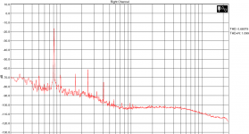
One way to design around the probem of high slew rate garbage at the input of the phonostage is passive EQ of the 75usec BEFORE it enters the amplification stage. I designed a passive inductive RIAA for ETF that does just that. By coincidence i even use the ADA4898 at the input. The reason i use it is, that it can swing 40mA clean so a feedback resistor of 300 Ohm can be used to limit the gain in the first stage. As funny as it looks, this stage works fine with the ceveat that the impedance of the cart. is known. In my case the 6 Ohm of my Titan i ( including losses in the connectors ) are tumed with a series resistor of 4 Ohm to have the required 75usec with a 0.75mH coil.
I put the coils in an oversized Mu-Metall can for low hum. Again this is a low Z design with 4 Ohm DC impedance. AC impedance goes up in the treble though so this is not exactly a zero ohm design.
I put the coils in an oversized Mu-Metall can for low hum. Again this is a low Z design with 4 Ohm DC impedance. AC impedance goes up in the treble though so this is not exactly a zero ohm design.
Attachments
One way to design around the probem of high slew rate garbage at the input of the phonostage is passive EQ of the 75usec BEFORE it enters the amplification stage. I designed a passive inductive RIAA for ETF that does just that. By coincidence i even use the ADA4898 at the input. The reason i use it is, that it can swing 40mA clean so a feedback resistor of 300 Ohm can be used to limit the gain in the first stage. As funny as it looks, this stage works fine with the ceveat that the impedance of the cart. is known. In my case the 6 Ohm of my Titan i ( including losses in the connectors ) are tumed with a series resistor of 4 Ohm to have the required 75usec with a 0.75mH coil.
I put the coils in an oversized Mu-Metall can for low hum. Again this is a low Z design with 4 Ohm DC impedance. AC impedance goes up in the treble though so this is not exactly a zero ohm design.
... and I can vouch that it sounds very good!
/OT: I see you made it home alright!
jan didden
Joachim -
try OPA627 (instead of OPA134) or even better OPA627+ buffer at the position of the 2nd opamp.
Best,
try OPA627 (instead of OPA134) or even better OPA627+ buffer at the position of the 2nd opamp.
Best,
Hi Joao,
I like passive RIAA, but not for the reason you cite.
Unfortunately, the "chronological" way of thinking about NFB is a classically flawed argument; one of the ones that leads to distrust and misunderstanding of NFB. Those time delays are microscopic compared to the period of the audio signal if the amplifier has a good high frequency gain crossover frequency and good stability.
The closest to truth that this way of looking at things comes is the Baxendall effect where Baxandall illustrated re-modulation in a feedback loop due to interactions between the fed-back signal and the input signal. I discuss this effect at length in my book. The effect is negligible in practice. It turns out that this effect actually pretty much disappears once the total amount of NFB around a nonlinearity exceeds about 15 dB. This amount of feedback INCLUDES any amount of feedback arizing from local degeneration. The Baxandall effect is a mathematical reality that has little or nothing to do with time delay.
Cheers,
Bob
Thanks Bob for explaining that. I know this because I had to learn this during my education .... I just liked to mention the "time delay" of the musical structure.
I don't think this is a correct way to look at it. Even if you have phase shift in the feedback loop (which you will get if you get high enough in freq) there is no 'delay' as implied here.
For instance, it is known that the voltage across a cap is shifted 90 degrees wrt the current into the cap.
If you use a sine wave current, the voltage is also a sine wave, 90 degrees phase shifted. It *looks* like a delayed input wave but it isn't.
Think about it: every minuscule change in the input current gives an *immediate* minuscule change in cap voltage. There is NO delay!
I tried to explain here:
http://www.diyaudio.com/forums/blogs/janneman/454-feedback-how-late-time-same-time-all-time.html
Let me know if I succeeded 😉
jan didden
Jan
This is true regarding the electrical circuit. My answer is the same I gave Bob, I'm speaking from the delay of the musical texture...
That's it.
But makes no sense to explain to people who do not have certain level of knowledge in circuit theory and feedback theory. Even real results would not convince them.
And, do not forget Jan, that marketing purposes require to protect and emphasize certain design philosophy. This is the one and only reason.
Mr. PMA
why do you offend me, do you know me, my knowledge or my education? Have you ever listened to any of my designs?
Why do you offend other peaople here? It looks that you're Mr. Know-It-All ...
I will not lower himself (down) to your niveau and discuss anything with you, especially music and it's reproduction. Anyway thank you for your kind words...
I wish you all the best for your live!
Yes Jan, i made it home safe at least to Cologne and we drive further to my home in Sauerland today.
I was surprised too how well my little passive phono sounded but i do not claim that this is my best efford. I found it apropriate for a DIY festival. It is another option and very easy to build because it is so simple. As far as i heard from Martina your female partner liked the sound of our system too.
PMA, i was sure that you spot the OPA134 at ones and when you read my original MPP thread you find that it is not my favourite Opamp eather. I use OPA827 and ADA4627 when i want a Fet input nowerdays but i had them only as SMD not soldered to an adaptor yet and time was running. Sorry for compromising.
Personally I think PMA is rather decent and I wouldn't get offended by statements like this. I think PMA maybe has a point.Mr. PMA
why do you offend me, do you know me, my knowledge or my education? Have you ever listened to any of my designs?
Why do you offend other peaople here? It looks that you're Mr. Know-It-All ...
I will not lower himself (down) to your niveau and discuss anything with you, especially music and it's reproduction. Anyway thank you for your kind words...
I wish you all the best for your live!
PMA, i was sure that you spot the OPA134 at ones and when you read my original MPP thread you find that it is not my favourite Opamp eather. I use OPA827 and ADA4627 when i want a Fet input nowerdays but i had them only as SMD not soldered to an adaptor yet and time was running. Sorry for compromising.
Joachim,
I am sorry but I have not reviewed the MPP thread, though I am of course aware of that thread.
IMO your choice of OPA827 and ADA4627 is perfect, sorry for any misunderstanding.
Best,
Some thoughts
Folks with a water dependency view an amplifier as a basin, having walls that become more rigid when frequency goes up.
At lower frequencies, the walls are so soft that waves are reflected without a phase shift.
At unity gain frequency, the walls become totally inflexible and reflected waves experience a 180 degree shift of phase.
The wall, and it's love affair with frequency level, is an intrinsic design feature of the amp, and nothing changes that.
The way you view an amplifier seems like regarding it as 1-on-1 with a water basin, while in reality it's a bouncing charge thing that doesn't require to generate a water ripple to travel the distance.
Mr Macura is an acoustic engineering EE, i'd be somewhat pee'd off if he replied it takes indepth knowledge about aquatic wave and ripple theory, but he's fully entitled to point out that fully understanding an electrical thing requires adequate theoretical background/teaching.
Last edited:
Mr. PMA
why do you offend me, do you know me, my knowledge or my education? Have you ever listened to any of my designs?
Why do you offend other peaople here? It looks that you're Mr. Know-It-All ...
I will not lower himself (down) to your niveau and discuss anything with you, especially music and it's reproduction. Anyway thank you for your kind words...
I wish you all the best for your live!
I don't think his post was offending. Just facts that can be seen clearly if one wants to look.
What did you find offending?
jan didden
- Status
- Not open for further replies.
- Home
- Member Areas
- The Lounge
- John Curl's Blowtorch preamplifier part II